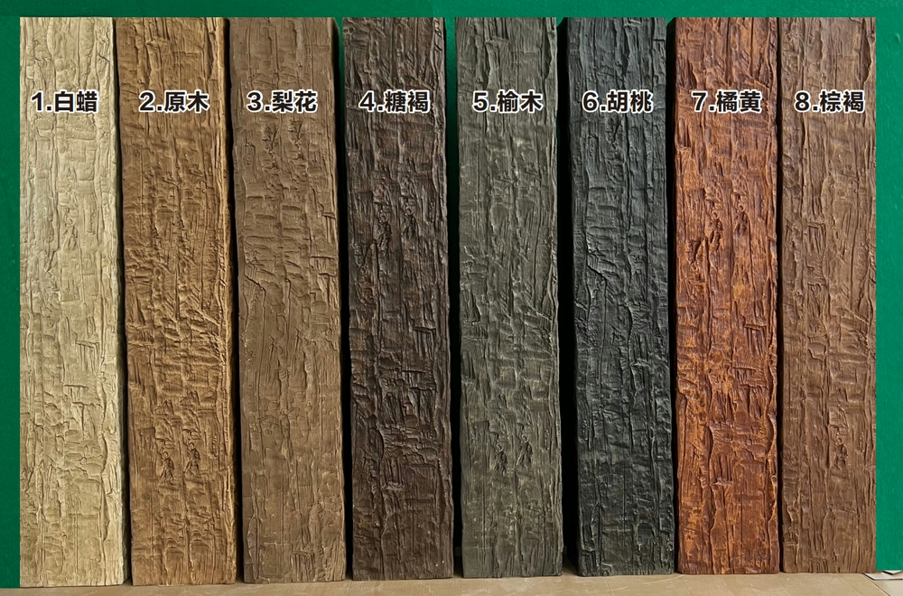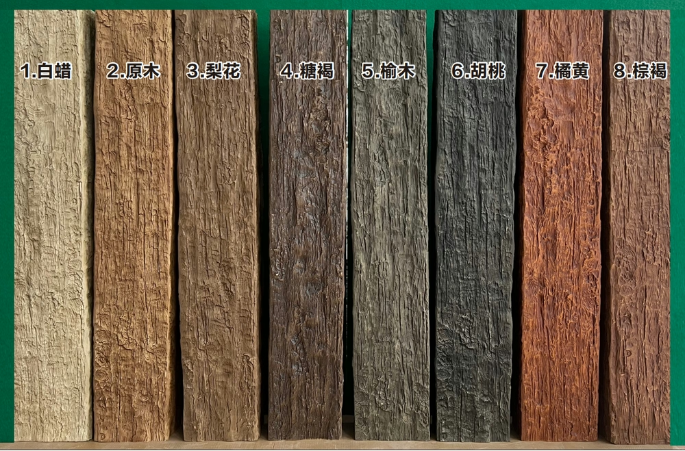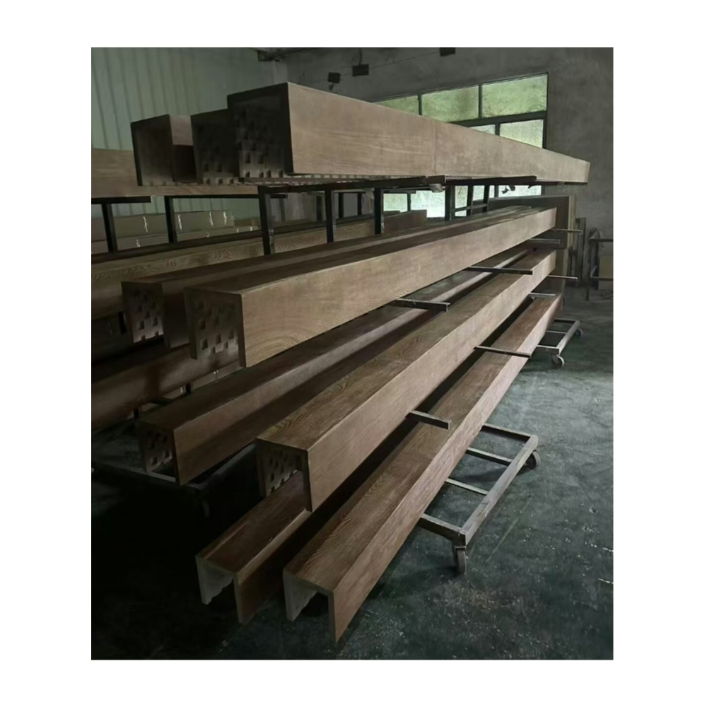
Decorative Hollow Ceiling Beams Polyurethane Faux Wood
Interior Installation: fauxwoodbeams 008
Architect Specification document Perspective
Specification section 09 65 19 - Resilient Faux Wood Beams. The following text is written in CSI format for use in architectural specifications where the design intent calls for the appearance of exposed timber but the construction documents require reduced weight, consistent dimensions, and predictable lead times. The decorative hollow profile referenced herein is intended for interior applications only unless specifically noted as exterior-rated.
Faux Wood Beam Installation
Specification section 09 65 19 - Resilient Faux Wood Beams. The following text is written in CSI format for use in architectural specifications where the design intent calls for the appearance of exposed timber but the construction documents require reduced weight, consistent dimensions, and predictable lead times. The decorative hollow profile referenced herein is intended for interior applications only unless specifically noted as exterior-rated.
writingStyle
architect-specification document
CSI Specification
Design Notes
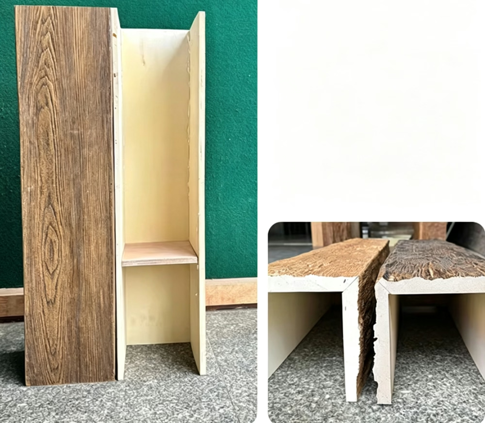
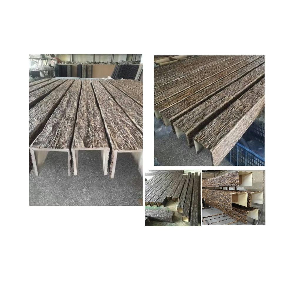
The hollow profile is preferred where the design intent allows for surface-mounted electrical, where ceiling structure cannot support the weight of solid timber, or where shipping cost to the project site makes solid alternatives impractical. For applications requiring the beam to span between supports without intermediate mounting, consult manufacturer for reinforcement options.
Frequently Asked Questions
Are faux wood beams realistic looking?
Yes, our faux wood beams feature hand-carved textures and multi-step finishing that captures every detail of authentic aged wood. Most people cannot tell the difference.
How much do these beams weigh?
Our faux wood beams are approximately 88% lighter than real wood. A typical 8-foot beam weighs only 10-15 pounds, making DIY installation easy.
Can I install these outdoors?
Yes, we offer outdoor-rated faux wood beams that are UV-resistant and waterproof, perfect for covered patios and porches.
How do I get a quote?
Click the "Get Inspired - Contact Us" button above. We typically respond within 2-4 hours with pricing tailored to your project.