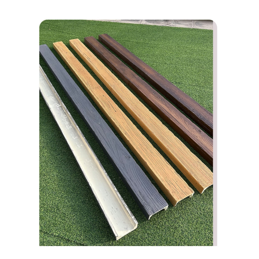
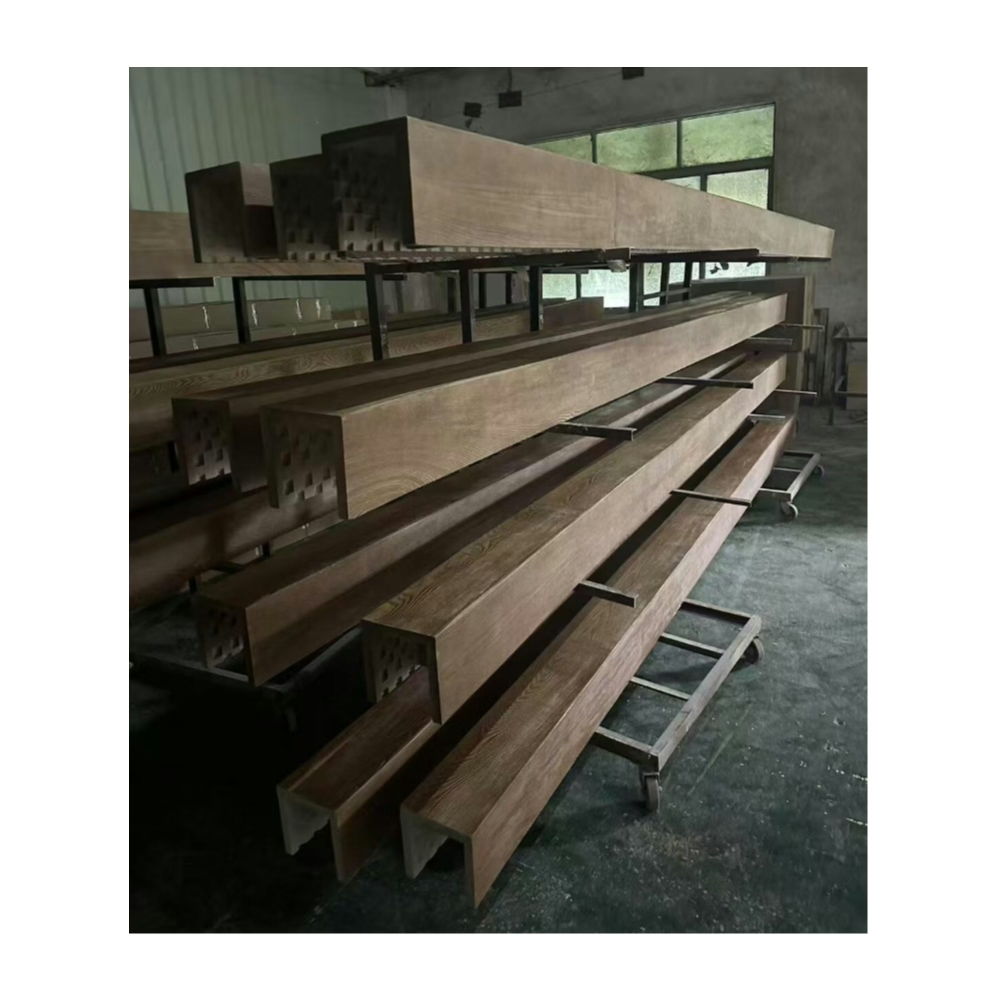
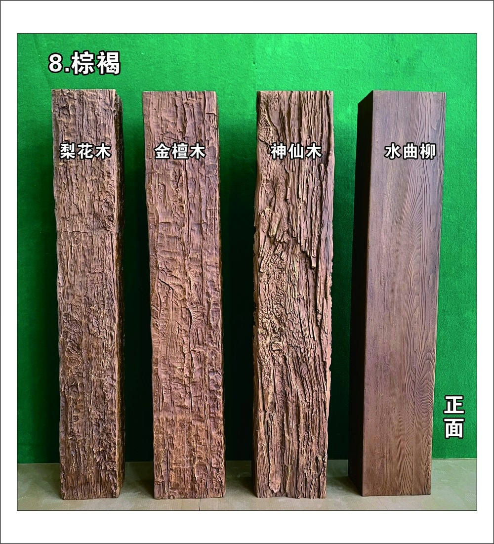
The converted warehouse loft had everything a design-conscious buyer wanted—soaring ceilings, abundant natural light, and authentic industrial character. Everything except the maze of exposed steel I-beams painted institutional gray that dominated the ceiling plane. The developer wanted to preserve the open-loft aesthetic while adding warmth and residential appeal, creating a design challenge that structural beam wrapping solves elegantly.
I've specified beam wrap systems for dozens of adaptive reuse projects where existing structural members need concealment or aesthetic transformation. Unlike purely decorative faux beams that attach to finished ceilings, wrap systems must accommodate the dimensional realities of structural members while maintaining proper clearances, allowing for thermal movement, and meeting fire safety requirements. Understanding these technical considerations separates successful installations from problematic ones.
Understanding Structural Beam Types and Wrapping Challenges
Steel I-beams present the most common wrapping scenario in commercial renovation work. These members come in standardized dimensions defined by their depth and flange width, ranging from compact W6 sections to massive W36 beams spanning large open areas. The cross-sectional shape creates a wrapping challenge—the flanges extending beyond the web create recesses that must be either filled or incorporated into the wrap system design.
Concrete beams typically feature rectangular cross-sections that simplify wrapping geometry but present weight-bearing challenges. A concrete beam might measure 12 inches wide by 24 inches deep, creating substantial surface area that requires secure attachment. The material itself doesn't accept fasteners reliably without specialized anchors, and drilling into structural concrete raises engineering concerns that require careful review.
Glulam and engineered wood beams occasionally need cosmetic enhancement even though they're already wood products. A structural glulam might provide necessary load capacity but lack the rustic character desired for a mountain lodge aesthetic. Wrapping allows transformation from utilitarian appearance to decorative finish without compromising structural function.
Box beams fabricated from steel or concrete often conceal utilities within their hollow cores. These members require wrap systems that allow future access to electrical, HVAC, or data infrastructure running through the beam cavity. Removable wrap panels or hinged access doors must integrate seamlessly with the overall design while providing maintenance access.
Design Considerations for Wrap Systems
Sizing calculations determine wrap component dimensions based on the structural member being concealed. For a W12x26 steel beam (12 inches deep, 12.2 inches flange width), the wrap system must create a finished appearance larger than these base dimensions. Adding 1.5 inches of clearance around the perimeter results in a finished beam approximately 15 inches wide by 15 inches deep, assuming a square wrap profile. This dimensional growth affects ceiling height and clearances that must be verified against building code requirements.
Profile selection influences both aesthetics and installation complexity. Simple rectangular wraps prove easiest to fabricate and install, making them cost-effective for large beam counts. Decorative profiles with chamfered edges, routed details, or hand-hewn textures add visual interest but increase material costs and installation labor. The profile choice should reflect the overall design intent and budget constraints.
Joinery details at corners determine visual quality and structural integrity. Miter joints create clean corner intersections but require precise cutting and leave visible seam lines. Lap joints prove more forgiving during installation but create slight shadow lines at overlaps. Purpose-manufactured corner pieces eliminate field joinery entirely, ensuring consistent appearance across multiple beams with reduced installation skill requirements.
Thermal expansion accommodation prevents wrap system failure in environments with significant temperature swings. Steel beams expand and contract measurably with temperature changes—a 30-foot steel beam might move nearly half an inch between summer and winter temperatures. Wrap systems must allow this movement without cracking, delaminating, or developing gaps. Flexible attachment methods using slotted holes or resilient mounting brackets address this requirement.
Material Selection for Different Applications
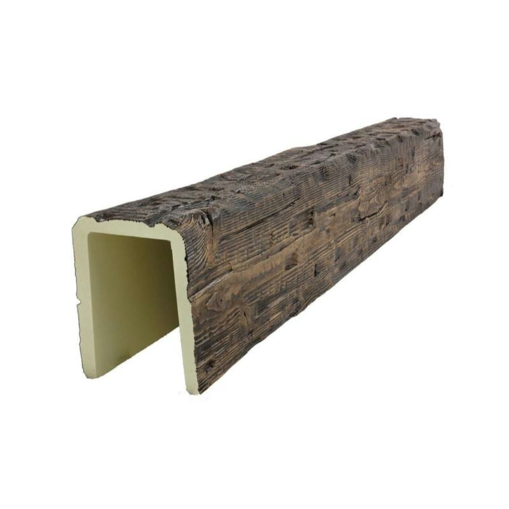
Standard polyurethane U-channel beams adapt readily to wrapping applications when structural dimensions align with available sizes. A W8 steel beam wraps neatly within a 10-inch or 12-inch PU beam, with the structural member hidden inside the decorative shell. This approach proves most cost-effective when standardized products match project requirements without extensive customization.
Custom-molded wrap components address non-standard structural sizes or profiles requiring specific decorative features. Manufacturers can produce three-sided U-channels dimensioned precisely to structural member sizes, eliminating gaps and reducing installation labor. Custom molding requires tooling investment that makes economic sense for larger projects with multiple identical beams but proves prohibitive for single-unit applications.
Multi-piece modular systems break complex wraps into manageable components that assemble around structural members. A typical four-piece system includes a bottom panel, two side panels, and a top cap that interlock using tongue-and-groove joints or mechanical fasteners. This modular approach allows one or two installers to wrap beams without heavy lifting equipment, reducing labor costs significantly.
Hybrid systems combining polyurethane decorative faces with structural backing materials offer advantages for specific situations. A plywood or MDF backer provides structural rigidity and fastener-holding capacity, while thin polyurethane facing delivers authentic wood appearance. This approach works particularly well for very large beams where solid polyurethane components would become prohibitively heavy or expensive.
Installation Methods and Attachment Strategies
Direct attachment to steel uses self-tapping metal screws or powder-actuated fasteners driven through wrap components into the structural member. This method provides secure mounting but requires access to fastener heads for installation, which may compromise aesthetic quality if fasteners remain visible. Countersunk screws filled with color-matched putty minimize visual impact while maintaining structural connection.
Cleat systems create an intermediate mounting surface that accepts standard fasteners while simplifying installation. Wood or aluminum cleats attach directly to structural members using appropriate fasteners for the substrate material. Wrap components then secure to these cleats using conventional screws, allowing positioning adjustments and easier disassembly if future modifications become necessary.
Adhesive bonding eliminates visible fasteners entirely when structural conditions allow. Construction adhesives formulated for polyurethane bonding create permanent connections between wrap components and structural substrates. This method requires clean, dry surfaces and adequate clamping during cure time. Adhesive-only attachment limits future disassembly options and may not satisfy code requirements for fire-rated assemblies.
Suspended systems hang wrap components from structural members using adjustable brackets or wire, creating an air gap between structure and decorative covering. This approach proves necessary when structural members require fire protection that wrap components would compromise. The air gap maintains the structural member's fire rating while providing desired aesthetic transformation.

Fire Rating and Code Compliance Issues
Fire-rated structural members must maintain their protective ratings after wrap installation. A steel beam with spray-applied fireproofing relies on that protection to maintain structural integrity during fire events. Wrapping this beam improperly could trap heat, reduce fire rating effectiveness, or violate code requirements. Building officials require documentation demonstrating that wrap systems don't compromise existing fire protection.
Listed assembly requirements apply when building codes mandate specific fire-resistance ratings for structural members. Some jurisdictions allow field-applied wraps over fire-rated structures if engineering analysis demonstrates continued compliance. Others require that the complete assembly—structure plus wrap—undergo fire testing and listing by recognized testing laboratories. Understanding local code requirements prevents costly redesign after installation begins.
Combustibility concerns arise with any decorative material near structural members. While polyurethane itself has fire performance characteristics, building codes classify materials and limit their use based on building type, occupancy, and location. High-rise residential buildings face stricter requirements than single-family homes. Working with code officials early in design prevents specification of materials that won't gain approval.
Smoke development and flame spread ratings quantify how materials perform during fire events. Building codes reference these standardized test results (ASTM E84) to establish acceptable materials for various applications. Premium polyurethane products carry flame spread ratings below 25, classifying them as Class A materials suitable for most applications. Lower-grade products may not meet code requirements for commercial construction.
Utility Coordination and Access Provisions
Electrical conduit routing often follows structural members, creating conflicts with wrap systems. A standard practice runs conduit along the bottom flange of steel beams, placing it directly in the path of wrap component installation. Coordination with electrical contractors determines whether conduit relocates, routes through wrap components via cutouts, or influences wrap system design to accommodate existing conditions.
HVAC ductwork and piping frequently attach to structural members for support. Large ducts may parallel beams with support hangers every few feet, while smaller pipes might clamp directly to beam flanges. Wrap systems must work around these attachments without compromising their function or requiring costly relocation. Access panels allow future service to mechanical systems without removing entire wrap assemblies.
Data and communications cabling increasingly runs through ceiling spaces, with structural members providing convenient support. Cable trays might mount to beam webs, while individual cables may tie-wrap to flanges. Understanding the full scope of utilities attached to structural members before designing wrap systems prevents installation conflicts and schedule delays.
Future access requirements deserve consideration even when no current utilities run through wrapped areas. Adding removable panels at strategic locations costs little during initial installation but provides valuable flexibility if future tenant improvements require utility routing. This forward-thinking approach particularly matters in commercial spaces with high tenant turnover.

Dimensional Planning and Field Verification
Site measurement accuracy determines wrap system success more than any other factor. Structural steel dimensions stamped on beam webs provide nominal sizing, but actual dimensions include flange width, web thickness, and any attachments like clip angles or plates. Measuring multiple beams reveals dimensional consistency—or variations that require accommodation in wrap system design.
As-built conditions differ from construction drawings more often than architects care to admit. That W12 beam shown on fifty-year-old drawings might actually be a W14, or structural reinforcement added over the decades might have increased effective dimensions. Field verification before ordering custom wrap components prevents expensive mistakes that only become apparent during installation.
Clearance calculations account for all protruding elements including bolt heads, welds, and structural connections. A single bolt head projecting 1.5 inches from a beam flange forces wrap system dimensions to increase accordingly, affecting ceiling height and potentially creating code compliance issues. Identifying these obstacles during site survey allows design adjustments before fabrication.
Alignment and level verification reveals structural realities that influence wrap system installation. Beams installed decades ago may sag slightly under long-term loading, creating bows that aren't apparent visually but affect wrap installation. Understanding these conditions allows installers to use shimming strategies that create visually straight wrap assemblies despite underlying structural irregularities.
Color Matching and Finish Coordination
Existing millwork coordination ensures new beam wraps integrate seamlessly with surrounding finishes. If crown molding, baseboards, or other trim elements carry specific stain colors or wood species appearance, beam wraps should match these references. Obtaining samples of existing finishes allows manufacturers to custom-match colors, creating cohesive design that appears original to the space.
Lighting effects change color perception significantly between sample viewing and installed appearance. A wrap color that appears perfect under fluorescent shop lighting might look entirely different under the LED downlights specified for the actual space. Reviewing samples under project lighting conditions prevents disappointing mismatches discovered during installation.
Aging considerations matter for projects incorporating both genuine wood elements and polyurethane replicas. Natural wood finishes darken over years of UV exposure, while polyurethane maintains consistent color indefinitely. Matching brand-new polyurethane to twenty-year-old wood elements requires adjusting colors to account for the natural wood's existing patina rather than matching its original appearance.
Grain direction consistency creates believable wood appearance across multiple beam wraps. Natural wood beams would show continuous grain running their length, so wrap systems should mimic this pattern. Random grain orientation or mismatched grain texture at joints immediately signals artificial materials to discerning observers.
Cost Factors and Budget Planning
Material costs scale with beam dimensions and complexity. Wrapping a compact W8 beam costs far less per linear foot than enclosing a massive W24 member simply due to material volume. Complex decorative profiles, custom colors, and special finishes add incremental costs that multiply across large beam counts. Value engineering during design development identifies opportunities to reduce costs without compromising visual quality.
Installation labor typically exceeds material costs for beam wrapping projects. Working overhead requires lifts, scaffolding, or staging that increases labor hours compared to floor-level work. Crew size and skill level influence productivity—experienced teams might install twice the linear footage per day compared to crews learning techniques on the job.
Access equipment rental represents significant expense for projects with numerous high-level beams. Boom lifts, scissor lifts, or rolling scaffolding may cost several hundred dollars per day, extending project duration directly impacts total equipment rental costs. Efficient installation sequencing minimizes equipment rental periods by grouping work to maximize daily progress.
Engineering and permitting fees apply to projects requiring structural analysis or code compliance documentation. Some jurisdictions mandate professional engineer review for any modifications to structural members, including purely cosmetic wrap systems. Understanding these requirements during budgeting prevents surprise costs that strain project finances.
Long-Term Maintenance and Durability
Cleaning requirements remain minimal for polyurethane wrap systems. Unlike real wood that absorbs moisture and stains, polyurethane surfaces wipe clean with standard household cleaners. Periodic dusting prevents accumulation that dulls surface appearance, while occasional washing with mild detergent maintains like-new appearance indefinitely.
Impact damage repair proves straightforward when wrap systems use mechanical fasteners rather than permanent adhesive. A damaged panel section removes and replaces without affecting adjacent components, making repairs practical and economical. Keeping spare material from original installation allows perfect color matching during future repairs.
Thermal cycling effects remain minimal with quality polyurethane formulations. Properly installed systems accommodate structural member movement without developing cracks, gaps, or fastener loosening. Annual inspection verifies continued performance, with any issues addressed promptly to prevent propagation.
Refinishing options exist if aesthetic preferences change over time. Polyurethane surfaces accept primers and paints readily, allowing complete color transformation without removing wrap systems. This adaptability extends useful life and allows spaces to evolve aesthetically without costly demolition and replacement.
Project Success Factors
Structural beam wrapping transforms utilitarian infrastructure into architectural features that enhance rather than compromise design intent. Success requires thorough site survey, careful material selection, proper installation technique, and attention to code compliance. Projects that invest adequate time in planning and coordination deliver results that appear built-in rather than added-on, creating value that justifies the investment.
For renovation architects and commercial contractors facing exposed structural members that challenge design objectives, polyurethane wrap systems offer proven solutions that balance aesthetics, performance, and budget constraints. The technology has matured to where installations routinely achieve results indistinguishable from solid timber construction while delivering superior durability and reduced maintenance.
Technical References
ASTM standards cited in every specification
Test Data
Lab results from internal testing program
Updated 2026
Reviewed against current product specs