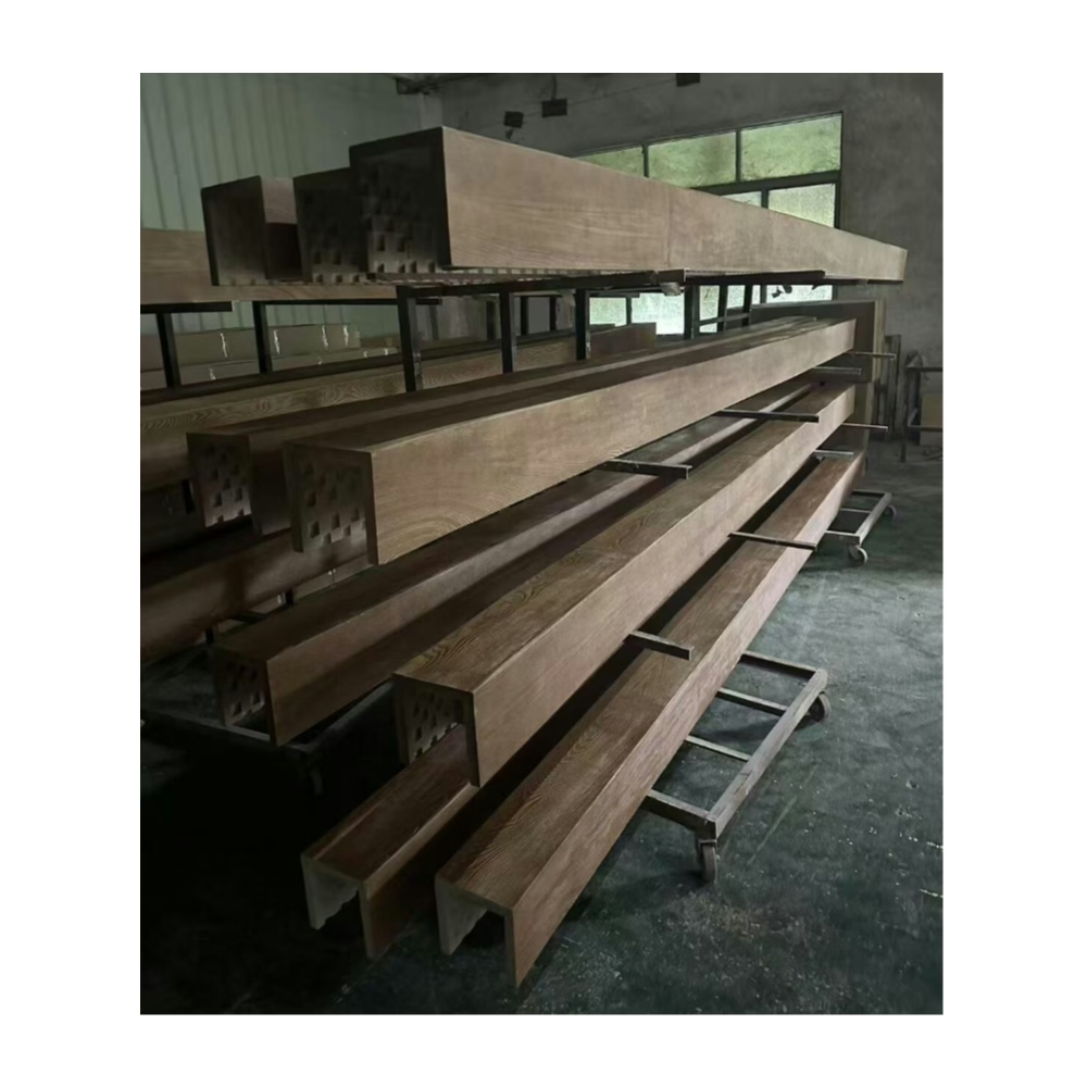
The dining room installation used five identical beams spaced mathematically equal across the 18-foot ceiling width. Yet something looked wrong—the end bays appeared narrower than center spaces despite identical measurements. The homeowner sensed the asymmetry immediately even without understanding why. We adjusted the layout, slightly widening end bays to compensate for the optical illusion that makes perimeter spaces appear compressed. The revised layout measured slightly unequal but appeared perfectly balanced—a lesson in how visual perception trumps mathematical precision when planning symmetrical beam arrangements.
Symmetrical ceiling layouts create ordered, harmonious compositions that human perception finds inherently pleasing. Yet achieving genuine visual symmetry requires understanding optical illusions, perspective effects, and contextual factors that make mathematically equal spacing appear unbalanced. Professional designers master these subtleties, producing layouts that feel effortlessly correct even when measurements reveal intentional asymmetries correcting for perceptual effects.
Fundamental Symmetry Principles
Bilateral symmetry creating mirror-image patterns around central axes forms the most recognizable symmetrical approach. A single beam centered in a room establishes vertical bilateral symmetry. Multiple beams spaced equally with a center beam maintains this organization. Human visual systems evolved detecting symmetry—faces, bodies, and natural forms exhibit bilateral symmetry that we instinctively recognize and find attractive.
Radial symmetry organizing elements around central points suits circular or octagonal spaces but applies less commonly to typical rectangular rooms. Coffered ceilings with beam grids crossing at right angles exhibit a form of radial symmetry where patterns read consistently from multiple viewpoints. Understanding when radial rather than bilateral symmetry serves design intent expands compositional possibilities.
Dynamic symmetry using mathematical proportions—golden ratio, Fibonacci sequences, harmonic ratios—creates balanced compositions that feel right without obvious geometric regularity. These proportional systems appear throughout classical architecture and natural forms. While more subtle than simple bilateral symmetry, dynamic symmetry creates sophisticated compositions rewarding closer attention.
Scale relationships between beam dimensions and spacing intervals affect visual balance. Heavy, massive beams demand generous spacing avoiding crowded appearance. Delicate beams tolerate closer spacing without overwhelming ceilings. The ratio between beam width and spacing intervals typically ranges from 1:4 to 1:8—an 8-inch beam might space at 32 to 64-inch intervals depending on desired density.
Rhythm and repetition through consistent spacing intervals create visual cadence across ceiling planes. Regular spacing produces march-like rhythms suited to formal spaces. Varied spacing creates syncopated rhythms with visual interest from irregular intervals. Understanding rhythm helps designers choose spacing strategies matching intended spatial character.
Mathematical Spacing Calculations
Equal division approaches divide room dimensions by desired beam quantities, creating uniform spacing. For a 16-foot room with four beams, dividing 192 inches by 5 (four beams creating five intervals) yields 38.4-inch spacing. This mathematical approach provides starting points requiring visual refinement accounting for perceptual effects and practical constraints.
Edge margin adjustments recognize that perimeter spaces often require different treatment than internal intervals. A common approach places outer beams one spacing unit from walls—if internal spacing is 40 inches, position first beams 40 inches from walls. Alternatively, half-spacing margins (20 inches in this example) tighten perimeter relationships creating more intimate scaling at room edges.
Odd versus even beam counts affect symmetry options. Odd beam quantities allow central beams establishing clear axes. Even quantities create central gaps that some designs benefit from—particularly when focal points like chandeliers occupy room centers. Understanding these implications guides beam quantity decisions during design development.
Dimensional adjustment for actual beam widths ensures that visual spacing—measured from beam edge to adjacent beam edge—matches intended dimensions rather than just center-to-center measurements. If beam centers space at 48 inches with 8-inch beam widths, actual gaps measure 40 inches. Planning should specify whether dimensions reference beam centers or edges, preventing confusion during installation.

Optical Corrections and Perceptual Adjustments
End bay expansion compensates for the perceptual effect making perimeter spaces appear compressed compared to internal intervals. Increasing outer spacing by 5-10% creates visual equality despite measured differences. This correction, known since classical antiquity, applies across architectural scales from column spacing to beam layouts. The effect intensifies in long, narrow rooms where perspective compression becomes pronounced.
Height-related adjustments account for how ceiling height affects perceived spacing. Low ceilings make closely spaced beams feel oppressive while the same spacing in high-ceilinged rooms appears comfortable. As rough guidance, spacing-to-height ratios between 1:1.5 and 1:2.5 work well—10-foot ceilings might support spacing from 4 to 6.5 feet. These ratios adjust based on beam scale and desired spatial character.
Perspective distortion correction addresses how beams appear closer together when viewed from acute angles. Beams running toward viewers converge perspectively, appearing more densely spaced in the distance. Gradually increasing spacing toward distant ends can counteract this effect in long galleries or corridors, though most residential rooms aren't long enough to warrant this sophisticated correction.
Light and shadow effects on spacing perception vary with lighting conditions. Beams under uniform ambient lighting read clearly in their actual spacing. Dramatic directional lighting creating strong shadows makes spacing intervals appear different than neutral lighting reveals. Evaluating proposed layouts under expected lighting conditions prevents surprises after installation.
Color and contrast impacts on visual weight affect optimal spacing. Dark beams against light ceilings appear heavier and denser than light beams on similar backgrounds. This perceptual weight influences comfortable spacing—dark beams might require wider intervals achieving visual balance equivalent to more closely spaced light beams. Sample mockups testing color combinations inform spacing decisions.
Contextual Factors Affecting Layout
Architectural features including windows, doors, fireplaces, and built-ins influence optimal beam placement. Beams aligned with or bracketing significant features create intentional relationships. Random placement that slightly misses alignment with features appears accidental rather than purposeful. Strong contextual alignment or clear independence both work—weak near-alignments create visual tension.
Furniture arrangement considerations prevent beams from awkwardly bisecting functional zones or creating uncomfortable relationships with major furniture pieces. A beam running through a dining table center creates visual organization. A beam positioned 12 inches off-center appears awkward. Understanding furniture layouts during beam planning creates cohesive designs where architecture and furnishings reinforce rather than conflict.
Lighting fixture coordination ensures that beams and fixtures create unified ceiling compositions. Centering chandeliers within beam-defined fields creates intentional framing. Recessed lighting aligned with beam intervals establishes organized patterns. Random relationships between lighting and beams create visual chaos undermining both systems. Early coordination between architectural and lighting design prevents these conflicts.
HVAC register and vent locations constrain beam placement in ways that architectural features don't—ductwork paths and structural attachments make registers essentially immovable. Successful layouts work around these fixed elements, perhaps using beams to define zones around registers or positioning beams to guide eyes away from utilitarian ceiling elements.
Structural ceiling conditions including joist directions and spans affect practical beam installation. Beams running perpendicular to joists attach easily at multiple points. Parallel beams require blocking or cleats spanning between joists. Understanding structural realities during layout planning prevents designs requiring extensive structural additions that could have been avoided through modest layout adjustments.

Room Shape Specific Strategies
Rectangular rooms with one dominant dimension benefit from beams spanning the shorter direction, visually widening narrow spaces. Alternatively, parallel beams running the long dimension emphasize length, suitable when accentuating linear progression serves design intent. The orientation decision affects perceived proportions significantly—spaces reading as too narrow benefit from cross-grain orientation, while those lacking directional emphasis benefit from parallel orientation emphasizing axes.
Square rooms lack obvious directional emphasis, offering either challenge or opportunity depending on perspective. Beam grids creating coffers suit square plans by establishing organizational frameworks where none existed. Diagonal beams across corners create dynamic compositions breaking static square geometry. Single beams bisecting squares create intentional asymmetry that can either energize or unbalance depending on execution quality.
L-shaped rooms resulting from additions or open-concept designs joining originally separate spaces benefit from beam layouts acknowledging the compound geometry. Beams might change direction at the transition, creating visual cues about spatial organization. Alternatively, continuous beams across transitions unify distinct zones into cohesive wholes. The choice depends on whether design intent emphasizes distinction or unity between joined spaces.
Irregular rooms with angled walls or non-orthogonal geometries challenge symmetrical planning. Options include ignoring irregularities, treating dominant rectangularity as primary and minor variations as inconsequential. Alternatively, embrace irregularity through beam layouts acknowledging and emphasizing geometric complexity. The latter approach requires design confidence and skill avoiding compositions that appear confused rather than intentionally complex.
Vaulted and cathedral ceilings with sloping planes add three-dimensional complexity to layout planning. Beams might run horizontally beneath slopes, emphasizing the contrast between level elements and angled planes. Following roof slopes creates cohesive visual flow but complicates installation and can make spaces feel lower than level beams would. Hybrid approaches combining horizontal and sloped beams create visual complexity requiring careful proportion development.
Multi-Beam Pattern Types
Parallel beams representing the simplest multi-beam approach work beautifully when proportion and spacing receive careful attention. This straightforward pattern suits most residential applications where complexity might overwhelm modest room scales. The pattern's simplicity creates timeless aesthetics unlikely to appear dated, making it safe default choice for risk-averse projects.
Grid patterns with beams crossing perpendicular create coffered ceiling effects dividing planes into rectangular fields. These grids suit formal spaces—dining rooms, studies, living rooms—where architectural gravitas enhances rather than conflicts with function. The complexity demands larger ceiling areas to succeed—grids in small rooms create cluttered appearance rather than elegant organization.
Herringbone or chevron patterns using angled beams create dynamic visual interest suited to contemporary aesthetics. These sophisticated patterns require precise layout and installation achieving clean miter joints at intersections. The effort involved generally restricts these patterns to feature areas or smaller ceilings where impact justifies complexity.
Border and field combinations use perimeter beams framing central ceiling areas that might remain clear or receive different treatments. This hierarchical approach suits formal rooms where definition matters more than uniform treatment. The border establishes room character while preserving central flexibility for lighting, ventilation, or future modifications.
Hybrid systems combining different beam scales or orientations create visual complexity and hierarchy. Primary beams at wide spacing establish dominant organization while secondary beams subdivide intervals creating layered rhythm. These sophisticated compositions require design skill preventing confusion, but when executed well deliver architectural richness exceeding simple uniform patterns.
Drawing and Documentation Methods
Hand sketching during conceptual phases allows rapid exploration testing multiple layout options efficiently. Sketches capture essential spatial relationships without requiring measured precision premature in concept development. This fast, iterative process cycles through possibilities quickly, identifying promising directions for detailed development.
Scaled floor plans with ceiling layouts overlaid enable dimensional verification ensuring that conceptual schemes work mathematically. These drawings confirm that beams fit within actual dimensions, spacing achieves desired intervals, and layouts work around architectural features. Scale drawings catch errors that sketches miss while remaining faster than full CAD documentation.
CAD modeling provides precision required for installation documentation while enabling three-dimensional visualization showing how layouts appear from various viewpoints. Perspective views from normal eye heights reveal how layouts read in practice versus abstract plan views. This 3D capability catches issues that plan-only design misses.
BIM integration for complex projects coordinates beam layouts with structural, mechanical, electrical, and other building systems in single comprehensive models. Clash detection identifies conflicts between beam suspension and ductwork, sprinkler lines, or structural members requiring resolution before installation begins. This coordination capability justifies BIM investment for larger commercial projects even when overkill for residential applications.
Physical mockups using temporary materials—cardboard, tape, or lightweight lumber—demonstrate proposed layouts at full scale allowing evaluation in actual spaces. This analog approach provides reality-testing that drawings can't match, revealing how layouts feel beyond how they look abstractly. Mockups particularly benefit challenging projects where confidence in drawn schemes remains uncertain.
Installation Layout Transfer Techniques
Baseline establishment creates reference lines from which measurements locate beam positions accurately. Snapping chalk lines parallel to walls at known distances establishes guides for perpendicular measurements. These baselines prevent accumulated errors that compound when measuring sequentially from one beam to the next.
Center point location marks room centers establishing primary axes for symmetrical layouts. Finding centers by measuring diagonals and marking intersections provides more accuracy than relying on room rectangularity which might not be perfect. Layouts referencing confirmed centers maintain symmetry despite irregular room geometry.
Story poles—straight boards marked with beam locations—transfer complex spacing patterns repeatably across ceiling lengths. Marking one story pole with complete layout then using it to mark ceiling positions ensures consistent spacing while eliminating repetitive measurements prone to error accumulation. This traditional technique remains valuable despite modern tools.
Laser levels project lines or points establishing references visible across rooms simultaneously. Rotary lasers create horizontal planes allowing marking multiple points at consistent elevations. Dot lasers project grids simplifying orthogonal layout work. These tools accelerate layout while improving accuracy compared to traditional methods.
Coordinate dimensions referencing two walls as zero points allow recreating layouts from numerical documentation rather than transferring from drawings. Recording X-Y coordinates for each beam position creates unambiguous documentation that different installers could independently execute achieving identical results. This precision matters for phased installations or future renovations requiring beam additions matching original layouts.
Quality Control and Verification
Progressive checking during layout prevents compounding errors by verifying accuracy at each step before proceeding. Confirm baseline accuracy before measuring from it. Verify first beam location before positioning second. This methodical approach catches mistakes early when correction costs little rather than discovering errors after installing multiple beams incorrectly.
Diagonal measurements verification checks layout rectangularity. For rectangular beam grids, diagonal measurements between opposite corners should be equal. Differences indicate skewed layouts requiring correction before proceeding. This simple check catches systematic errors that visual inspection misses.
Spacing uniformity confirmation measures each interval verifying consistency meeting design intent. While some variation proves acceptable—1/4 inch across 4-foot spans negligibly affects appearance—larger inconsistencies create visible irregularity. Documenting measurements creates records supporting quality claims or identifying installation defects requiring correction.
Visual evaluation from multiple viewpoints assesses whether measured layouts achieve intended visual effects. Viewing from primary approaches, room centers, and various angles reveals how layouts read in practice. This evaluation sometimes identifies adjustments improving visual quality despite meeting numerical specifications—appearance ultimately matters more than measurement compliance.
Common Layout Mistakes to Avoid
Over-complication through excessive beam quantities or pattern complexity creates visual chaos rather than sophisticated organization. Residential rooms rarely benefit from more than five beams—greater quantities make ceilings feel busy and lower. Restraint consistently delivers superior results compared to maximalist approaches.
Ignoring contextual features by treating ceilings as abstract planes without relationship to walls, windows, or architectural features creates disconnection. Successful layouts acknowledge and respond to context whether through alignment, bracketing, or clear independence from features. Weak near-alignments appearing accidental undermine layouts that might otherwise succeed.
Inadequate margin spacing positioning beams too close to walls creates cramped perimeter relationships. Providing adequate breathing room—typically 20-48 inches depending on overall spacing—allows walls and ceilings to read as distinct planes rather than uncomfortably compressed. This margin particularly matters in rooms with crown molding or other trim establishing defined wall-ceiling transitions.
Mismatched scales specifying delicate beams in grand rooms or massive beams in modest spaces creates proportion failures undermining layouts regardless of spacing accuracy. Beam dimensions should match room scales—larger rooms accept and often require substantial beams, while smaller spaces demand restraint in beam sizing regardless of personal preferences for dramatic elements.
Failing to account for beam width when calculating spacing creates layouts where visual intervals don't match intentions. Planning based on center-to-center measurements might create tighter visual spacing than desired once beam widths consume interval portions. Thinking in terms of clear spaces between beams rather than abstract center-to-center dimensions prevents this disconnect.
Achieving Visual Harmony
Symmetrical layout planning for multiple beam installations requires balancing mathematical precision with visual perception, acknowledging that measured equality doesn't guarantee visual balance. Understanding optical effects, contextual factors, and proportional relationships enables creating layouts that feel effortlessly correct—the hallmark of successful design that appears simple only because underlying complexity resolves invisibly.
For designers and installers working on multi-beam projects where visual quality determines success, mastering symmetrical layout principles separates amateur execution from professional results. The investment in careful planning, mathematical verification, and perceptual refinement produces ceiling treatments that enhance spaces for decades, justifying the attention during brief design and installation phases.
Technical References
ASTM standards cited in every specification
Test Data
Lab results from internal testing program
Updated 2026
Reviewed against current product specs