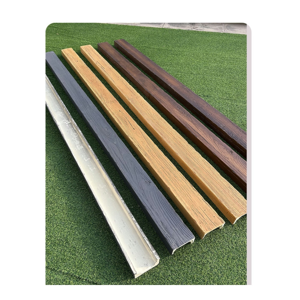
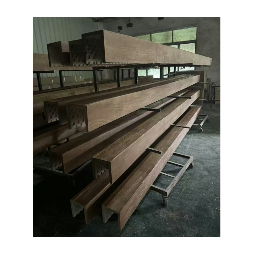
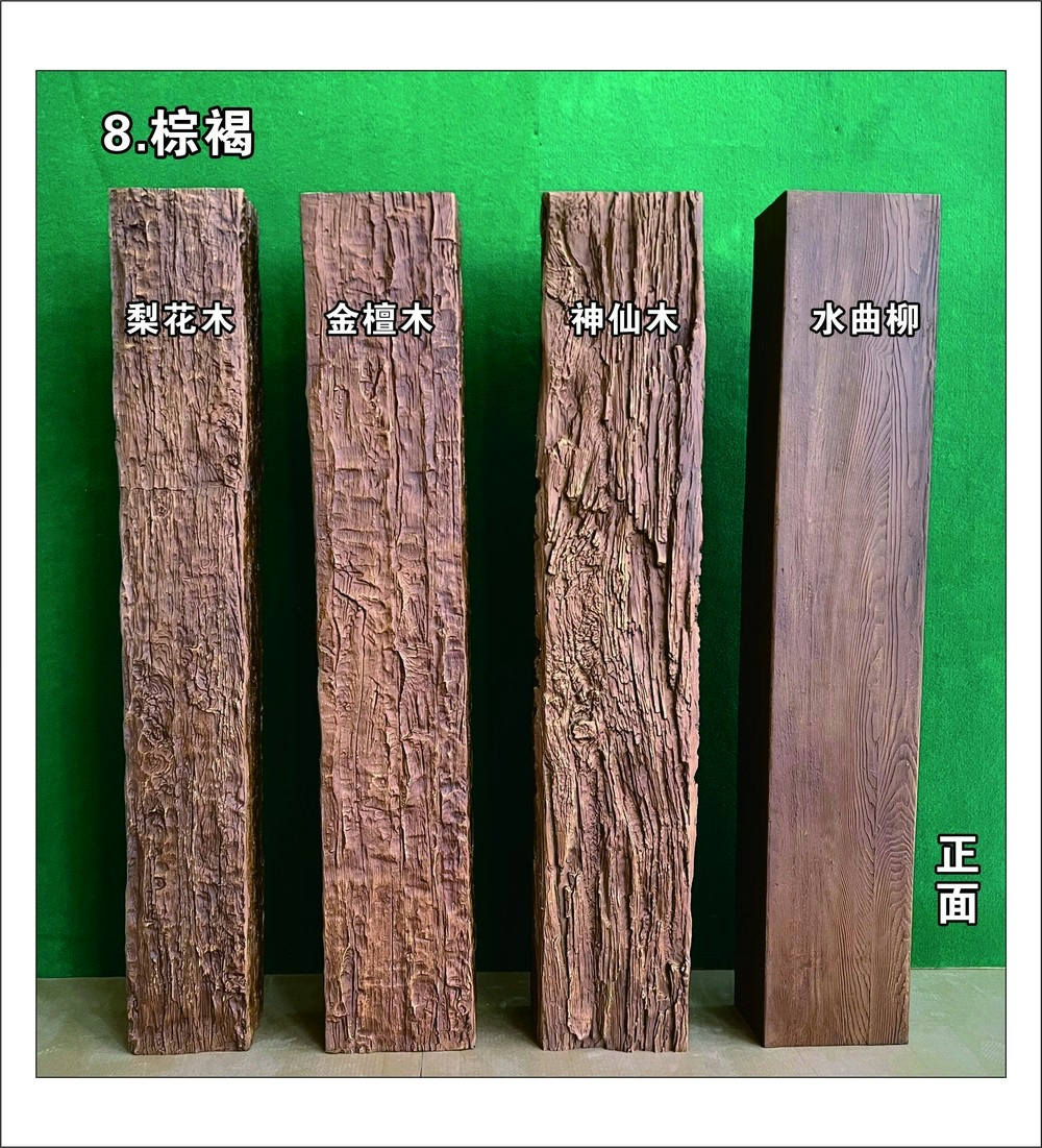
The 30-foot beam spanning the great room looked perfect at installation in July—tight joints, uniform appearance, securely fastened every 24 inches. By January, the homeowner called reporting cracks near fasteners and visible gaps at the center splice joint. Investigation revealed that the beam had contracted nearly 3/8 inch as winter cold dropped room temperature from 78°F to 62°F. Our fastening pattern, appropriate for shorter beams, had restrained thermal contraction creating stress concentrations that cracked the polyurethane. We redesigned the mounting using slotted fastener holes and flexible adhesive allowing movement, then replaced the damaged beam. That expensive lesson taught me that thermal expansion isn't just an engineering abstraction—it's a physical reality that installations must accommodate.
All materials expand when heated and contract when cooled. While polyurethane exhibits relatively low thermal expansion compared to metals, dimensional changes across long spans and substantial temperature ranges become significant enough to damage installations that don't accommodate movement. Understanding thermal expansion coefficients, calculating anticipated movements, and designing installation systems allowing controlled movement prevents failures while maintaining attractive, secure installations.
Understanding Thermal Expansion Physics
Coefficient of thermal expansion (CTE) quantifies how much materials expand per degree of temperature change, typically expressed in inches per inch per degree Fahrenheit or millimeters per meter per degree Celsius. Polyurethane's CTE ranges from 30-50 × 10⁻⁶ in/in/°F depending on formulation—meaning a 100-inch beam expands 0.003 to 0.005 inches per degree temperature increase. While seemingly trivial, these small increments accumulate across long spans and wide temperature ranges into significant movements.
Temperature range determination requires understanding both seasonal extremes and daily variations in actual installation environments. Climate-controlled residences might experience 10-15°F seasonal variation between summer and winter thermostat settings. Unconditioned spaces like garages or three-season rooms might see 60-80°F seasonal swings. Daily variations from morning lows to afternoon peaks add short-term movement cycles overlaying seasonal changes.
Beam length directly affects total expansion—longer beams experience proportionally greater absolute dimensional change even though CTE remains constant. A 6-foot beam expanding 0.004 inches per degree across 20°F change moves 0.48 inches total. A 20-foot beam under identical conditions expands 1.6 inches—more than three times the shorter beam's movement. This relationship explains why thermal accommodation proves critical for long spans but often unnecessary for short beams.
Differential expansion between beams and supporting structures creates stress when materials with different CTEs attach rigidly. Polyurethane beams attached to wood framing experience similar expansion rates since wood and polyurethane have comparable CTEs. Beams mounted to concrete or steel structures encounter differential expansion since these materials expand differently than polyurethane. Understanding substrate materials affects mounting system design.
Constraint effects occur when mounting systems prevent free thermal expansion, converting temperature-induced dimensional changes into internal stresses rather than movement. Fully constrained beams can't expand, causing compression stresses that might buckle beams or pull fasteners through material. During contraction, constraint creates tension stresses that can crack polyurethane or separate adhesive bonds. Proper design allows controlled movement preventing stress accumulation.
Calculating Anticipated Movement
Design temperature range selection determines worst-case expansion calculations. Conservative approaches use extreme temperature ranges—perhaps 40°F to 90°F for climate-controlled spaces or 0°F to 110°F for unconditioned environments. Using actual anticipated ranges rather than theoretical extremes prevents over-designing for conditions that won't occur while ensuring adequate accommodation for realistic scenarios.
Expansion calculation using the formula ΔL = L × CTE × ΔT provides anticipated movement where ΔL represents length change, L equals original length, CTE is the thermal expansion coefficient, and ΔT represents temperature change. For example, a 16-foot (192-inch) beam with CTE of 40 × 10⁻⁶ in/in/°F experiencing 50°F temperature swing: ΔL = 192 × 0.00004 × 50 = 0.384 inches total expansion.
Safety factors applied to calculated movements account for CTE variability, temperature uncertainty, and installation imperfections. Multiplying calculated movement by 1.25 to 1.5 provides design margins ensuring systems accommodate actual conditions despite imperfect predictions. This conservatism proves particularly important when failure consequences prove severe or expensive.
Directional considerations recognize that linear beams expand primarily along their lengths with minimal width or depth changes. Mounting systems must accommodate longitudinal movement while potentially constraining perpendicular movement maintaining beam alignment. This directional freedom requires intentional design—allowing movement where needed while restricting it where beneficial.
Multi-segment calculations for beams joining multiple sections treat each section as independent expansion element. A 24-foot beam created from two 12-foot sections joined at center expands from each fixed point toward the joint. Each section expands half the total single-beam expansion, creating movement at the joint equal to combined expansion of both segments. Understanding multi-section behavior prevents joint details inadequate for actual movement.

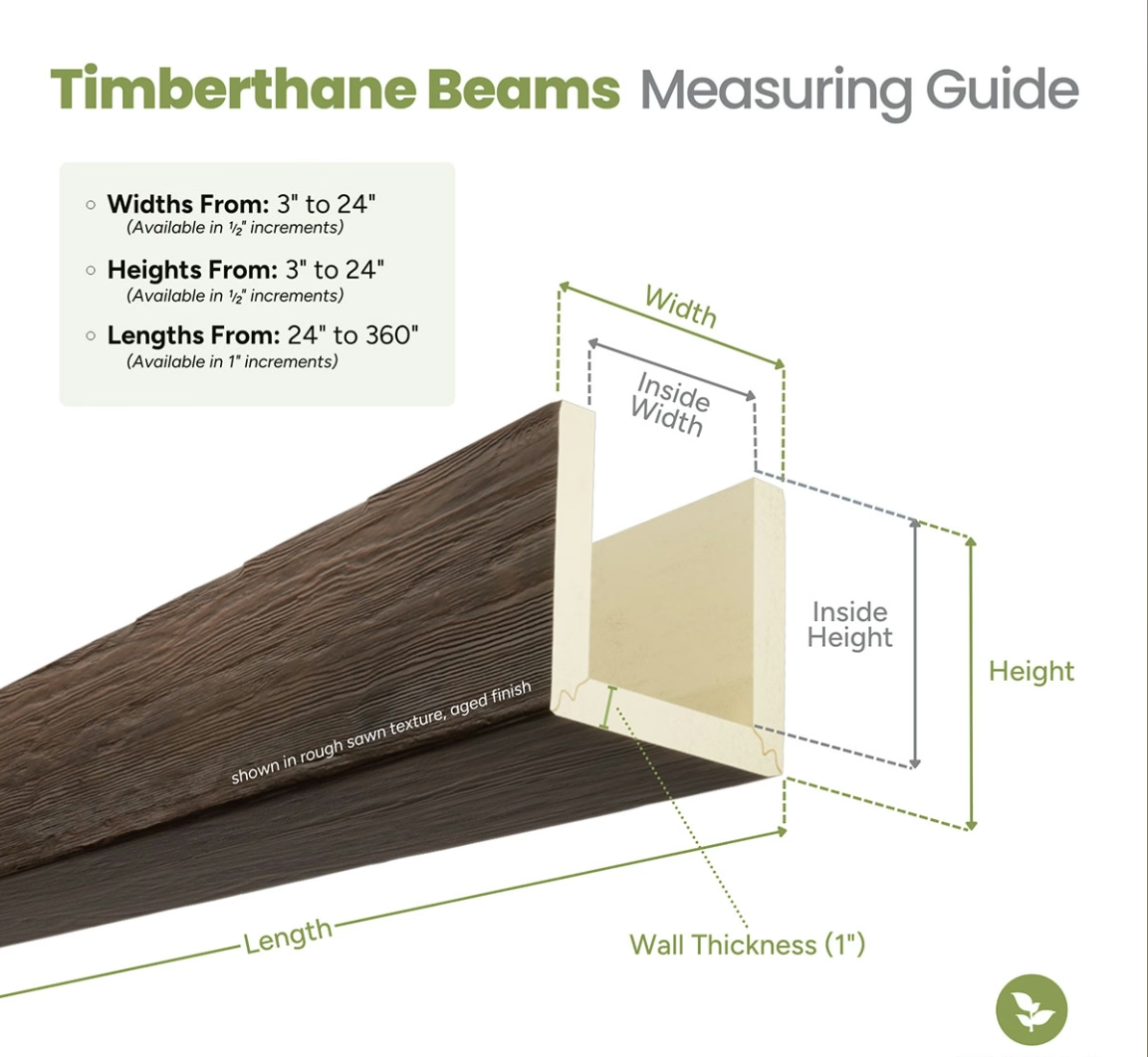
Expansion Joint Design and Detailing
Joint location planning positions movement accommodation joints strategically within beam spans. Center joints in long single beams allow symmetrical expansion from fixed endpoints. Multiple joints distributed along very long spans prevent any single joint from accommodating excessive movement. Joint locations should consider aesthetics—positioning joints at ceiling features, architectural transitions, or lighting locations makes them less visually apparent.
Joint width sizing must accommodate full anticipated expansion plus installation clearances and construction tolerances. If calculations predict 0.4 inches movement, providing 0.6-inch joint width allows expansion plus margin for installation imperfection. Undersized joints close completely during expansion, creating compression that damages beams or mounting systems. Oversized joints might appear visually excessive when beams contract.
Concealment strategies using trim, recessed details, or architectural features minimize joint visibility while allowing adequate movement. Battens covering joint gaps create shadow lines that hide movement while adding decorative detail. Recessed joints where beam ends meet in deeper ceiling reveals become less apparent than surface joints. Color-matched flexible sealants filling joints create visual continuity while accommodating movement.
Sealing materials must remain flexible across temperature ranges without hardening, cracking, or losing adhesion. Silicone and polyurethane sealants maintain flexibility indefinitely, making them suitable for expansion joints. Latex caulks harden over time, losing flexibility that leads to cracking. Sealant selection affects long-term joint performance as much as initial design.
Trim cap systems using decorative covers concealing joints while allowing underlying beam movement separate visual appearance from structural accommodation. Caps might attach to one beam section, floating over the adjacent section, or mount independently allowing both beams to move beneath fixed covers. These sophisticated systems deliver clean appearance despite substantial underlying movement.
Flexible Mounting System Design
Slotted fastener holes oriented parallel to beam lengths allow longitudinal movement while fasteners remain engaged. Holes elongated 1/4 to 1/2 inch longer than fastener shanks permit movement without fastener loosening. This simple technique accommodates thermal expansion using conventional fasteners without specialized hardware, though appearance suffers if fasteners remain visible.
Oversized washers or fender washers prevent fasteners from pulling through slotted holes during beam movement. Standard washers might not bridge slot widths adequately, allowing fasteners to disengage. Washers sized to cover slots regardless of fastener position within slots maintain secure attachment throughout movement cycles.
Flexible adhesive mounting using elastomeric construction adhesives allows bonded beams to move relative to substrates without bond failure. These adhesives stretch and compress accommodating movement while maintaining adhesion. Selecting adhesives specifically formulated for movement joints rather than rigid structural bonding proves essential. Manufacturer technical data should specify allowable movement capabilities.
Sliding cleat systems using mounting blocks that beams clip onto rather than fasten through create mechanical attachment allowing movement. Cleats might use spring clips, sliding channels, or other mechanisms holding beams securely while permitting longitudinal sliding. These sophisticated systems deliver clean appearance without visible fasteners while accommodating thermal expansion.
Fixed point strategy establishes one secure mounting location preventing beam movement, with all other attachments allowing controlled sliding. The fixed point typically positions at beam midpoint or one end, with movement occurring away from the anchor. This approach creates predictable movement patterns simplifying joint and fastener design.
Material Selection Considerations
Low-CTE polyurethane formulations minimize expansion for applications where movement accommodation proves difficult. Some manufacturers offer formulations with CTE approaching 25 × 10⁻⁶ in/in/°F—nearly half standard formulations. These specialized materials cost more but reduce expansion by 40-50%, potentially eliminating need for expansion accommodation in marginally long spans.
Composite construction combining materials with different expansion characteristics might intentionally balance expansion behaviors. However, differential expansion between laminated materials can cause delamination, making this approach generally problematic for thermal accommodation. Understanding material compatibility prevents creating composite structures that self-destruct through thermal cycling.
Substrate material consideration affects mounting system design since differential expansion between beams and substrates creates relative movement at interfaces. Polyurethane beams on wood framing expand similarly, minimizing relative movement. Beams on concrete or steel experience differential expansion requiring flexible mounting accommodating dissimilar material movement.
Finish material selection including paints or stains should consider thermal cycling effects. Brittle finishes might crack as beams expand and contract. Flexible coatings accommodate movement without damage. Understanding finish flexibility prevents cosmetic failures from thermal cycling even when structural systems handle movement adequately.
Installation Techniques for Movement Accommodation
Clearance maintenance during installation ensures that design clearances transfer to field execution. Installers might instinctively eliminate gaps, pushing beam sections tight together rather than maintaining specified clearances. Clear documentation and inspection verify that joints maintain designed spacing allowing anticipated expansion.
Fastener torque control prevents overtightening that constrains movement despite slotted holes or flexible mounting systems. Fasteners tightened excessively compress flexible mounting materials eliminating their accommodation capability. Specifications should note appropriate torque limits or qualitative tightness descriptions—"snug but not fully tight" allowing movement.
Seasonal installation timing affects initial joint sizing since beams install at specific temperatures within overall service range. Installing during moderate temperatures centers movement range around installation condition. Installing during temperature extremes positions beams at range limits, creating one-directional movement risk. Understanding installation temperature helps predict joint behavior through seasons.
Adhesive application patterns for flexible mounting systems should emphasize continuous beads rather than intermittent spots. Continuous adhesive distributes stress evenly during movement while spot bonding creates stress concentrations. Bead patterns should allow movement while providing adequate bond area—typically running lengthwise rather than crossing beam widths.
Special Considerations for Specific Environments
Unconditioned spaces including garages, barns, and three-season rooms experience temperature extremes requiring generous expansion accommodation. Design for these environments should use maximum anticipated temperature ranges and consider multiple expansion joints even in moderate-length beams. The broader temperature swings create movements exceeding climate-controlled space calculations significantly.
Commercial kitchens with cooking equipment generating substantial heat might experience localized temperature extremes beyond general building conditions. Beams near ovens, griddles, or other heat sources require special consideration for elevated operating temperatures. Shielding heat sources or relocating beams proves preferable to designing for extreme localized heating.
Geographic climate zones affect design temperature ranges and accommodation requirements. Northern climates with cold winters see larger temperature ranges than moderate coastal regions. Desert environments experience dramatic daily cycles but moderate seasonal variation. Understanding regional climate patterns informs realistic thermal design parameters.
Retrofit applications in historic buildings might preclude ideal expansion accommodation due to substrate limitations or preservation requirements. These challenging scenarios might require compromising—using shorter beam sections to minimize expansion, selecting low-CTE materials, or accepting higher risk of thermal stress while monitoring performance.
Monitoring and Maintenance
Seasonal inspection programs checking joint conditions, fastener engagement, and beam integrity verify that thermal accommodation systems perform as designed. Annual inspection ideally occurring during temperature extremes—mid-winter and mid-summer—observes systems at maximum expansion and contraction. This monitoring catches developing problems before they cause significant damage.
Joint condition assessment looks for sealant cracking, excessive gap opening beyond design limits, or gaps closing completely indicating inadequate accommodation. These observations reveal whether design assumptions matched reality or require adjustment. Early detection allows corrective action before damage accumulates.
Fastener inspection verifies that slotted holes still allow movement and that fasteners haven't loosened or pulled through material. Periodic tightening might be necessary as materials compress over time or fasteners work loose through movement cycles. However, retightening must respect torque limits preserving movement capability.
Crack detection around fasteners or at splice joints indicates excessive thermal stress that accommodation systems didn't adequately address. Small surface cracks might prove cosmetic, but progressive cracking suggests systematic problems requiring intervention. Documentation through photography tracks whether cracks remain stable or worsen over time.
Corrective Actions for Failed Installations
Fastener pattern modification reducing constraint points allows previously restricted beams to move more freely. Removing every other fastener or switching solid fastening to slotted holes reduces constraint. This retrofit requires careful structural analysis ensuring that reduced fastening still provides adequate support against gravitational loads.
Joint insertion cutting existing continuous beams to create expansion joints accommodates movement in installations that didn't originally include joints. This invasive correction requires structural support for newly created beam ends and cosmetic joint treatments concealing cuts. While effective, joint insertion proves labor-intensive compared to proper initial design.
Flexible adhesive injection between beams and substrates using foam or flexible sealants can provide some movement accommodation in adhesive-bonded installations experiencing thermal stress. This approach proves most effective in early failure stages before significant cracking develops. Severely damaged installations might require complete beam replacement.
Environmental modification reducing temperature extremes through improved climate control, insulation, or shading eliminates root causes rather than treating symptoms. If feasible, this approach prevents thermal stress more reliably than accommodation systems. However, environmental modification often proves impractical or expensive relative to installation corrections.
Design Software and Calculation Tools
Spreadsheet calculators implementing thermal expansion formulas enable rapid evaluation of different scenarios—various beam lengths, temperature ranges, and material properties. Creating reusable templates standardizes calculations while reducing errors from manual computation. These simple tools provide adequate capability for most installations without sophisticated engineering software.
Finite element analysis for complex installations with multiple interacting thermal, structural, and constraint factors reveals stress distributions and movement patterns that simplified calculations miss. FEA proves overkill for straightforward installations but justifies its complexity for critical applications, unusual geometries, or situations where failure consequences warrant detailed analysis.
CAD integration linking thermal expansion data to design drawings creates installation documentation showing fastener patterns, joint locations, and clearance requirements derived from actual thermal calculations rather than generic details. This integration ensures design intent transfers to construction documents rather than losing itself in abstract calculations divorced from actual installation plans.
Cost-Benefit Analysis
Accommodation system costs including specialized fasteners, flexible adhesives, or trim details exceed simple rigid mounting expenses. However, these incremental costs prove minimal compared to failure correction expenses. A $200 investment in slotted holes and flexible sealant prevents thousands in damaged beam replacement and installation labor.
Risk assessment weighing failure probability against consequence severity determines appropriate investment in thermal accommodation. High-visibility installations in expensive projects justify conservative designs with generous accommodation even if over-designed for actual conditions. Utility spaces or residential applications might accept higher risk with simpler, less expensive accommodation.
Long-term performance value of proper thermal design manifests through decades of trouble-free service rather than immediate cost savings. Owners rarely notice successful thermal accommodation—beams simply work as expected. Failure creates callbacks, repairs, and reputation damage that far exceed initial accommodation investments. This long-term perspective justifies proper design despite incremental costs.
Professional Engineering Responsibility
Thermal expansion accommodation in long-span beam installations requires engineering analysis rather than rule-of-thumb approaches or hoping that problems won't occur. Understanding expansion physics, calculating anticipated movements, and designing systems allowing controlled movement prevents failures while ensuring attractive, durable installations. For installers and designers working on projects with beams exceeding 12-16 feet or experiencing wide temperature ranges, systematic thermal expansion analysis proves essential to professional practice and long-term installation success.
专业的安装需要综合考虑热胀冷缩效应,通过科学计算和合理的伸缩缝设计,确保长跨度梁在温度变化下保持稳定和美观。
Technical References
ASTM standards cited in every specification
Test Data
Lab results from internal testing program
Updated 2026
Reviewed against current product specs