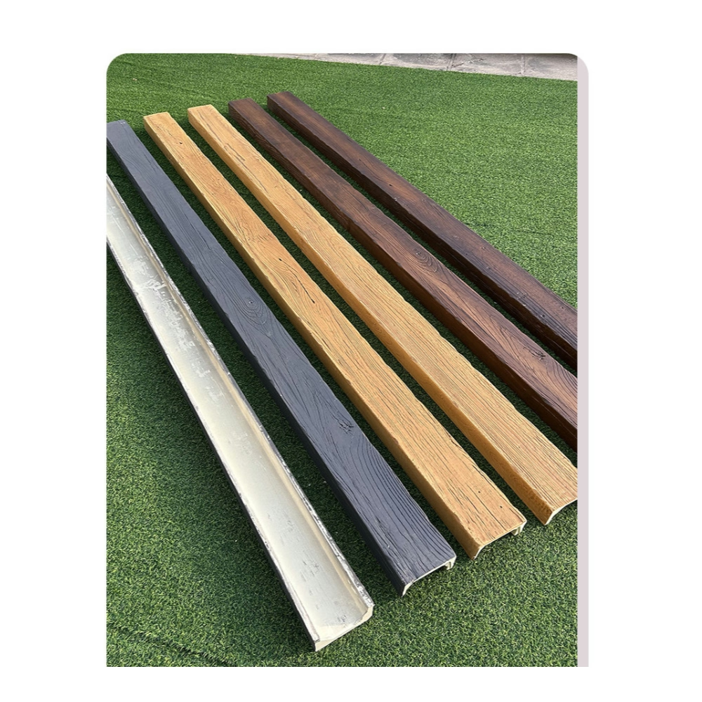
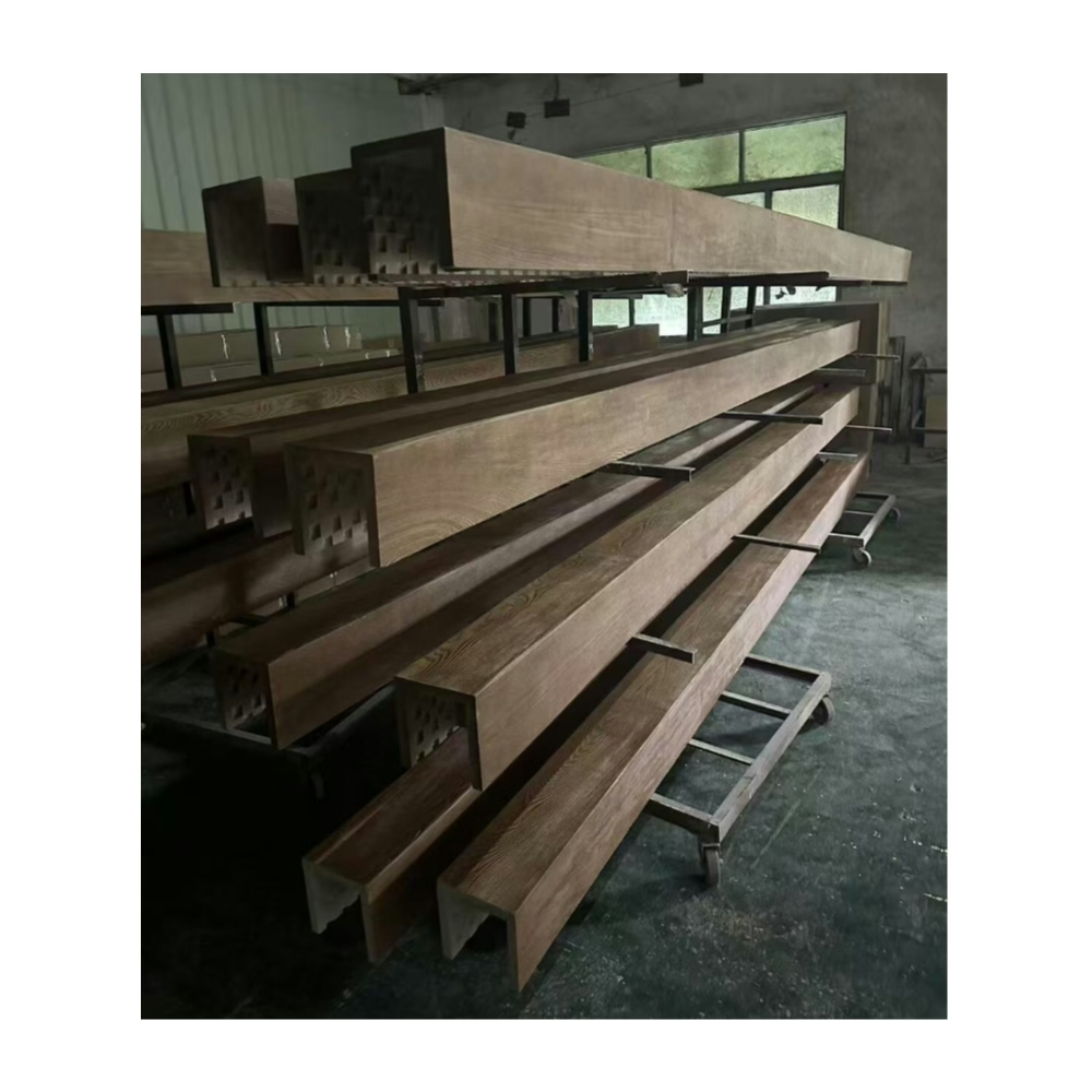
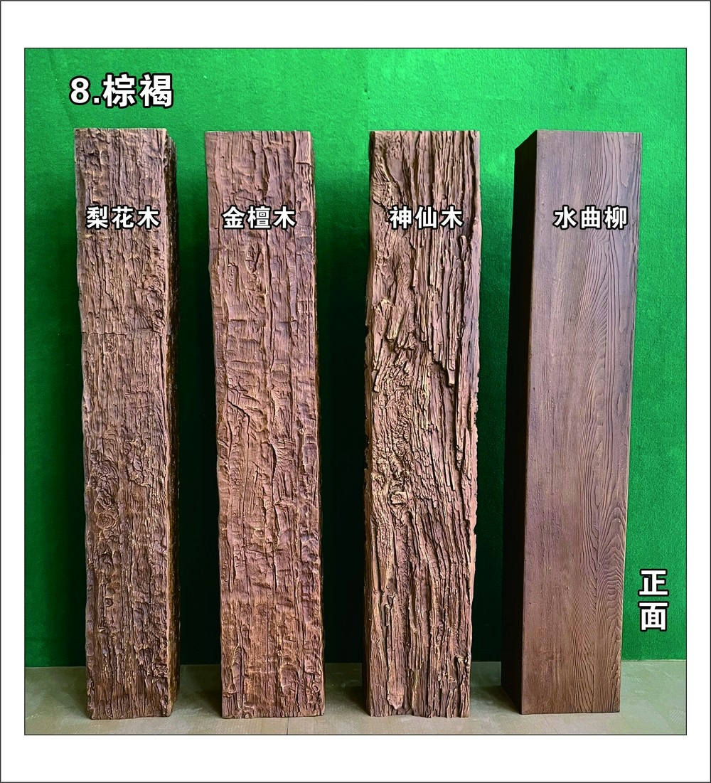
The conference center's grand hall featured 24-foot beams spanning the width without intermediate support—an impressive architectural statement. Six months after installation, gaps appeared at beam ends where they met wall trim. Winter heating had contracted beams enough that quarter-inch gaps opened at termination points that had fit tightly during summer installation. The installer hadn't accounted for thermal expansion, rigidly mounting beams that needed accommodation for seasonal movement. We added flexible trim details concealing gaps while allowing continued movement, but the lesson was clear: long-span installations in environments experiencing temperature variation require expansion compensation regardless of material type.
Thermal expansion—dimensional changes with temperature variation—affects all materials to varying degrees. While polyurethane exhibits relatively low thermal expansion compared to many materials, long spans accumulate enough total movement to create visible problems when installations don't accommodate expansion. Understanding expansion coefficients, calculating expected movement, and designing mounting systems that allow expansion without creating stress or visible gaps separates professional long-span installations from amateur work that looks good initially but develops problems across seasonal cycles.
Understanding Thermal Expansion Fundamentals
Coefficient of thermal expansion (CTE) quantifies how much materials expand per degree of temperature change, typically expressed in inches per inch per degree Fahrenheit or millimeters per meter per degree Celsius. Polyurethane typically exhibits CTE around 30-50 x 10⁻⁶ in/in/°F—meaning a beam expands 0.000030 to 0.000050 inches per inch of length for each degree Fahrenheit temperature increase. While this seems negligible, across long lengths and wide temperature ranges, the cumulative movement becomes significant.
Temperature range determination establishes the maximum expansion/contraction cycle materials will experience. A beam installed at 70°F might experience 40°F in unheated winter spaces and 95°F during summer heat, representing a 55°F range from coldest to warmest conditions. Understanding actual service temperature ranges requires considering building conditioning, sun exposure, and seasonal variations rather than assuming stable room temperature conditions.
Material property variations mean different polyurethane formulations exhibit different expansion rates. Rigid structural foams typically expand less than flexible formulations. Filled materials incorporating inert particles exhibit lower expansion than unfilled polymers. Product-specific data from manufacturers provides accurate values rather than generic assumptions about "polyurethane" that might not match actual products.
Cumulative expansion calculation multiplies length times temperature change times CTE, yielding total dimensional change. For a 20-foot (240-inch) beam with CTE of 40 x 10⁻⁶ in/in/°F experiencing 50°F temperature swing: 240 × 50 × 0.000040 = 0.48 inches total movement. Nearly half-inch dimensional change demands accommodation in mounting design.
Directional expansion occurs primarily along length axis since beams constrain less in this direction than across width or depth. Cross-sectional expansion proves negligible for most applications—width and depth changes of 0.02 inches go unnoticed. Length changes of half-inch create visible gaps or buckling depending on mounting constraints.
Calculating Expected Movement
Project-specific temperature analysis determining actual conditions materials will experience provides more accurate movement predictions than generic assumptions. Monitoring building temperatures across seasons reveals actual ranges. Historical weather data combined with building envelope analysis predicts interior temperatures in unconditioned or partially conditioned spaces. This analysis effort scales with project criticality—small residential jobs might assume generic ranges while major commercial projects justify detailed analysis.
Worst-case scenario calculations using maximum credible temperature ranges provide conservative designs accommodating extremes even if typical conditions prove more moderate. Designing for 60°F ranges when typical conditions vary only 40°F creates systems with safety margins absorbing unexpected conditions. This conservatism proves particularly valuable in unconditioned spaces where temperatures might exceed original assumptions.
Installation temperature recording documents conditions during beam mounting, establishing baseline from which expansion and contraction will occur. Beams installed during 85°F summer weather will predominantly contract during subsequent cooler periods. Those installed during 45°F winter conditions will primarily expand as temperatures rise. Understanding installation temperature relative to service temperature range predicts whether movement will be primarily expansion or contraction from installed condition.
Multiple beam interaction in grid patterns or parallel installations requires considering whether beams expand independently or whether mounting systems create interaction. Independent beams each accommodate their own expansion. Rigidly connected beams must share available expansion space, potentially doubling movement at shared interfaces. Design must account for cumulative effects in interconnected systems.

Mounting System Design Strategies
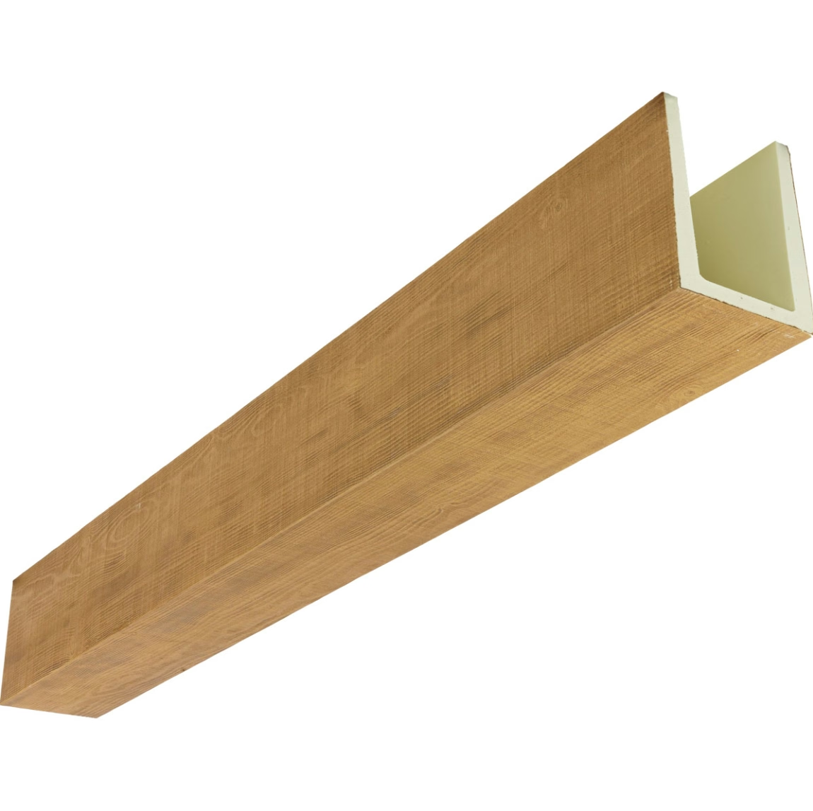
Slotted fastener holes allow beams to slide along mounting surfaces as they expand without creating stress. Holes elongated in the beam's longitudinal direction permit movement while maintaining vertical support. Fastener placement in slot centers during installation allows movement in either direction depending on whether temperatures rise or fall from installation conditions. This simple technique accommodates expansion in many applications without complex details.
Flexible mounting clips using spring characteristics or deformable materials accommodate movement while maintaining attachment. These specialized clips absorb dimensional changes through elastic deformation rather than requiring sliding. While more expensive than slotted holes, clips eliminate sliding friction concerns and work well where positive attachment throughout movement proves desirable.
Fixed-and-floating point systems anchor beams rigidly at one location while allowing free movement at opposite ends. The fixed point establishes position reference while floating ends slide as temperature changes. This approach concentrates all movement at floating ends rather than distributing it across length. Clear identification of fixed versus floating points during installation prevents accidentally restraining floating ends.
Adhesive-and-mechanical hybrid systems using flexible adhesive bonds throughout with mechanical fastening only at fixed points allow adhesive to deform accommodating movement. Construction adhesives exhibit some elasticity permitting minor movement without bond failure. However, relying on adhesive elongation alone works only for limited movement—large expansion requires mechanical accommodation.
Expansion joint integration where very long beams join mid-span incorporates designed gaps accommodating half the total expansion at each joint. Trim pieces or flexible sealant conceal gaps while allowing movement. This approach allows using standard-length beams for very long spans rather than requiring custom single-piece beams while providing defined movement accommodation.
Joint Design and Detailing
Scarf joints where beam ends meet at angles create less visually obvious transitions than square-cut butt joints. Scarfing joints at 15-30 degree angles distributes appearance changes across longer distances as gaps open or close with temperature cycles. The longer transition makes movement less noticeable than abrupt butt joints where small gaps become very obvious.
Trim reveal details using applied moldings at beam ends conceal gaps between beams and adjacent surfaces. Trim pieces attach to walls rather than beams, creating visual terminations that remain stationary while beams move behind them. Quarter-round, cove, or custom trim profiles sized to cover maximum anticipated gaps provide elegant concealment.
Flexible sealant joints filled with silicone or polyurethane caulk accommodate movement while maintaining continuous appearance. Proper joint design includes bond breaker tape preventing three-side adhesion that would stress sealant beyond its capability. Joint width should be twice the expected movement, allowing expansion to compress sealant to half width and contraction to stretch it to double width—both within sealant capability.
Sliding overlap joints where beam ends telescope slightly create positive visual appearance without relying on tight fits that thermal movement will compromise. One beam extends past joint point while the other fits inside, creating overlap that accommodates movement. While requiring more complex fabrication, this approach maintains clean appearance through all temperature conditions.
Keyed joints using interlocking profiles mechanically connect adjacent beams while allowing longitudinal sliding. Keys prevent vertical displacement while permitting expansion movement. This sophisticated approach suits applications requiring both visual and mechanical continuity across joints despite thermal movement requirements.
Substrate Interaction Considerations
Differential expansion between beams and ceiling substrates creates relative movement that mounting systems must accommodate. If ceiling materials expand more than beams, mounting must allow sliding preventing ceiling expansion from compressing beams. If beams expand more than ceilings, mounting must prevent beams from buckling as they grow against constrained ceilings.
Multi-material assemblies combining polyurethane beams with wood blocking, metal fasteners, and gypsum ceilings experience complex interactions as each material expands differently. Wood exhibits higher expansion perpendicular to grain than parallel. Metals vary widely—aluminum expands roughly twice as much as steel. Gypsum shows minimal expansion. Design must consider the entire assembly rather than just beam properties in isolation.
Friction forces between beams and mounting surfaces resist sliding, creating stress that can overcome adhesive bonds or fastener holding power if mounting doesn't accommodate friction. Smooth contact surfaces, adequate clearances, and appropriate fastener selection reduce friction allowing movement without creating damaging forces. Lubrication using dry lubricants at sliding interfaces might be appropriate for extremely long spans with high friction.
Beam weight on slopes creates gravitational forces supplementing or opposing thermal movement depending on slope direction and whether expansion moves beams upslope or downslope. Beams on upward slopes require secure mounting preventing gravitational sliding. Those on downward slopes might slide from gravity alone if friction proves inadequate. Combined thermal and gravitational effects require analysis in sloped applications.
Environmental Factors Affecting Expansion
Solar heating in sunrooms or spaces with significant glazing creates localized temperature elevations far exceeding ambient conditions. Direct sun striking dark-colored beams can raise surface temperatures 30-40°F above room air temperature. This solar gain creates expansion exceeding calculations based only on air temperature. Shading analysis or worst-case surface temperature assumptions prevent under-designing expansion accommodation.
HVAC system effects including hot or cold air discharge directly onto beams create temperature variations across beam lengths. A beam with one end near a heat register might experience 15°F temperature difference between ends, creating differential expansion where one end moves significantly while the other remains relatively stable. Understanding HVAC layout during design prevents these unexpected conditions.
Seasonal patterns in most climates create annual cycles where beams installed in one season will expand or contract to maximum extent six months later at opposite seasonal extreme. Installations should anticipate this cycle rather than assuming conditions will remain near installation temperature. Mid-season installation—spring or fall—positions beams near average temperature, minimizing maximum movement in either direction.
Humidity effects on dimensional stability primarily affect natural wood but can subtly influence some polyurethane formulations. While much less significant than thermal effects, moisture absorption causing swelling adds to dimensional changes in humid environments. Comprehensive analysis accounts for both thermal and moisture effects though thermal typically dominates.
Installation Best Practices
Pre-installation conditioning brings materials to installation environment temperature before mounting, establishing stable baseline dimensions. Staging beams in installation spaces 24-48 hours allows thermal equilibrium. Installing materials fresh from transport might mean they're 30°F colder or warmer than space conditions, appearing to expand or contract after installation as they reach ambient temperature. This apparent movement represents temperature equalization rather than service temperature cycling.
Temperature recording during installation documents baseline conditions and aids troubleshooting if movement problems develop later. Simple notation—"installed at 68°F, clear weather"—provides context for understanding subsequent performance. Digital photographs with EXIF data capture timestamps allowing correlation with weather records if needed.
Movement documentation through deliberate gap creation or measurement provides quantifiable verification that designs perform as intended. Installing beams with 1/8-inch gaps at floating ends, then measuring gaps seasonally verifies expansion calculations. If gaps close during summer and open beyond original dimension in winter, movement occurs as predicted. Unexpected behavior suggests design revision needs.
Installer training ensuring field crews understand expansion accommodation intent prevents well-designed systems from failing due to installation errors. Crews accustomed to tightly fitting everything might "fix" designed gaps or slots by forcing tight fits that eliminate expansion capability. Clear installation documentation and crew briefings prevent defeating design intent through misguided workmanship.
Troubleshooting Movement Problems
Buckling symptoms including bowing, ripples, or visible deformation indicate inadequate expansion accommodation. Beams constrained at both ends buckle when they can't accommodate expansion through lengthening. Diagnosis involves verifying mounting restraints at both ends and measuring temperature conditions versus original design assumptions. Remediation requires releasing one end or cutting beams to reduce constrained length.
Gap development at interfaces where tight fits existed initially suggests contraction from installation temperature. If gaps appear soon after installation, materials cooled from installation conditions. If gaps develop seasonally, thermal cycling exceeds accommodation. Remediation depends on gap size—small gaps might accept cosmetic filling, larger gaps require trim details or design modifications increasing accommodation.
Fastener pull-out where mechanical attachment fails might result from beams sliding against friction generating forces exceeding fastener holding capacity. Diagnosis examines fastener specification, substrate condition, and sliding resistance. Remediation might involve larger fasteners, reduced friction through smooth interfaces, or conversion to floating mounting eliminating constrained sliding.
Adhesive bond failure at beam edges particularly at ends indicates movement stressing bonds beyond capacity. Adhesive systems lacking adequate elongation capability fail when thermal movement stretches bondlines excessively. Remediation requires either more flexible adhesives or reducing bondline stress through modified mounting limiting adhesive reliance on accommodating movement.
Stress cracking in beams themselves represents the most serious movement-related failure, indicating that internal stresses from constrained expansion exceeded material yield strength. This failure mode suggests significant design errors—inadequate expansion accommodation combined with excessive temperature ranges or material properties not matching assumptions. Complete redesign and beam replacement typically proves necessary.
Special Considerations for Extreme Applications
Unconditioned spaces including garages, warehouses, or seasonal structures experience wider temperature ranges than conditioned interiors. Summer peak temperatures might reach 110°F while winter lows drop to 20°F—a 90°F range doubling movement compared to typical conditioned space analysis. Extra-conservative expansion accommodation prevents problems in these challenging environments.
Exterior applications exposed to full weather extremes require maximum expansion design even though polyurethane typically installs only in protected exterior conditions. Dark colors absorbing solar heat experience the most severe temperature cycles. Light colors reduce solar gain moderately. Understanding actual expected temperatures rather than assuming protected conditions ensures adequate design.
Historic building retrofits often involve long-span beams in spaces with deteriorating climate control or no conditioning. Original design conditions might have assumed heating and cooling that no longer functions reliably. Designing for wider temperature ranges than currently exist provides margin if climate control further degrades.
Cold climate installations in northern regions experience temperature ranges potentially exceeding typical design assumptions. Unheated spaces might experience temperatures matching outdoor conditions—dropping below 0°F in extreme climates. While these low temperatures rarely combine with summer peaks in the same space, understanding actual conditions prevents under-designing.
Hot climate installations in desert or tropical regions experience both extreme heat and in some cases significant day-night temperature swings. Attics in these climates routinely exceed 130°F on summer afternoons. Even shaded exteriors might reach 110°F. Local experience guides realistic temperature assumptions better than generic recommendations.
Documentation and Specification Requirements
Design calculations documenting expected movement, accommodation methods, and installation requirements should appear in construction documents. This technical backup supports design decisions and provides contractors information necessary for proper installation. Calculations need not be exhaustive—single-page summaries with key assumptions, results, and design requirements suffice for most projects.
Expansion joint schedules identifying locations, types, and sizes of joints designed into installations help contractors understand design intent. Schedule notations such as "Joint J1: 1/4" flexible sealant joint at grid lines A.1 and C.3, allow ±1/8" movement" communicate design clearly. Coordinating schedules with drawings ensures complete communication.
Installation specifications including fastener placement instructions, floating-versus-fixed end identification, and material conditioning requirements translate design intent into executable instructions. Specifications might state "Install beams with fasteners in center of slotted holes, allowing equal movement in either direction. Maximum tightness: snug plus 1/4 turn—do not over-tighten preventing sliding."
Inspection requirements defining what to verify during installation and what constitutes acceptable installation provide quality control basis. Requirements might specify verifying gap dimensions, confirming floating ends remain unrestrained, or measuring fastener positions in slots. Clear requirements enable meaningful inspection rather than generic visual checks.
Future Developments and Technology
Smart materials exhibiting minimal thermal expansion or actively compensating for temperature effects might eventually eliminate expansion accommodation requirements. Shape-memory alloys or engineered composites with near-zero CTE would allow long spans without expansion joints. Current development focuses on aerospace and precision instruments, but building materials might eventually benefit from these technologies.
Predictive maintenance systems monitoring building temperatures and beam positions might someday alert building managers if movement exceeds design assumptions or if restraints develop preventing designed movement. IoT sensors tracking gap dimensions, temperatures, and beam positions would provide data enabling proactive intervention before problems develop.
Advanced modeling software allowing designers to simulate thermal cycles and resulting stresses could optimize expansion joint locations and sizing more precisely than manual calculations. Building Information Modeling increasingly incorporates thermal analysis capability. Extending this to decorative elements remains future development opportunity.
Engineering Discipline in Design
Thermal expansion compensation in long-span beam installations demands engineering discipline calculating expected movement and designing accommodation systems adequate for service conditions. The physics of thermal expansion prove immutable—ignoring them doesn't prevent movement, it only ensures that movement creates problems. Professional installations succeed by respecting material properties and environmental realities through thoughtful design enabling reliable long-term performance.
For architects, engineers, and installers working on projects with beams spanning more than 12 feet or in environments experiencing significant temperature variation, understanding and accommodating thermal expansion prevents failures that compromise aesthetics and sometimes structural integrity. The modest design effort and minor cost increments for proper expansion accommodation prove trivial compared to callback costs and reputation damage from movement-related failures.
Technical References
ASTM standards cited in every specification
Test Data
Lab results from internal testing program
Updated 2026
Reviewed against current product specs