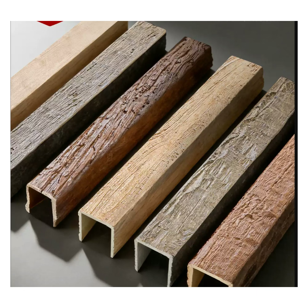
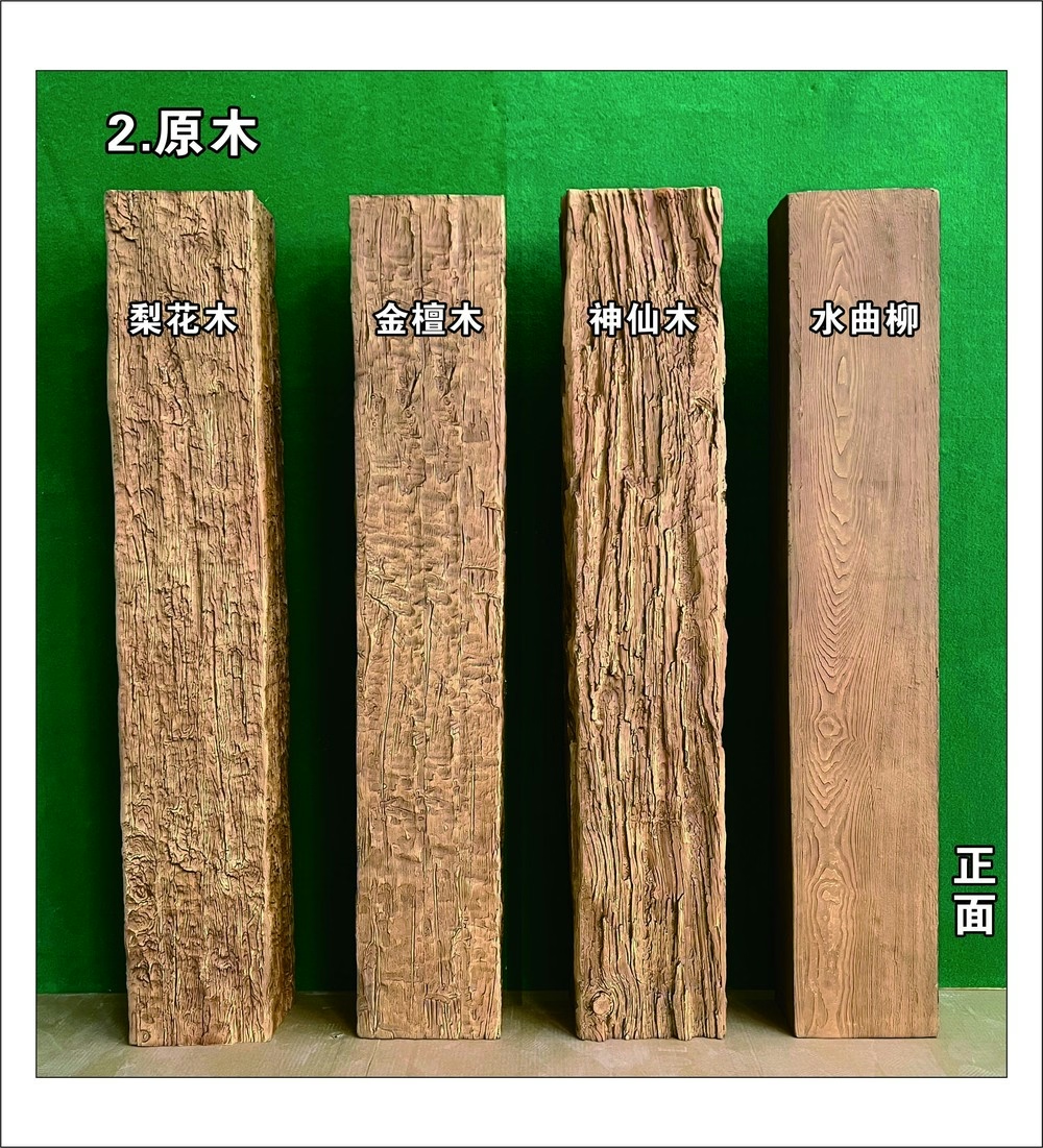
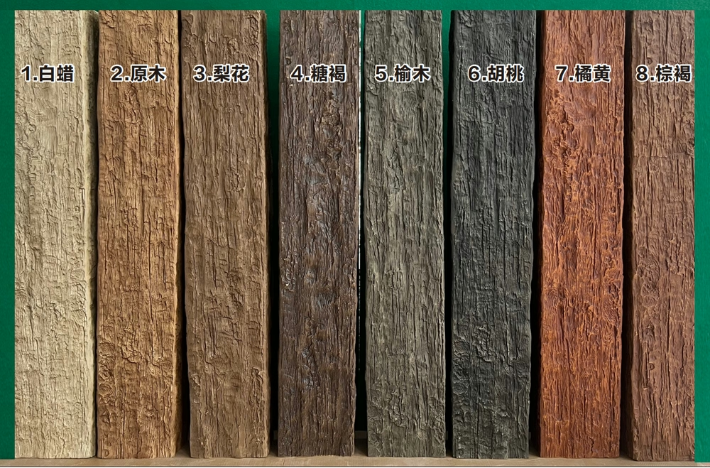
The 32-foot great room beam looked perfect at installation completion—straight, level, properly attached. Six months later, the center showed visible sag—nearly an inch of deflection creating an obvious curve that embarrassed everyone involved. The manufacturer's specification sheet clearly stated 16-foot maximum unsupported span, but the design required the continuous beam look without visible intermediate supports. We'd gambled that careful installation would prevent the sag that specification limits warned about, and we lost. The correction required installing concealed internal reinforcement—work that would have been far simpler to execute during original installation than as a remedial fix requiring beam removal and reinstallation.
Understanding sag mechanisms, span limitations, and reinforcement strategies allows designing long-span installations that maintain appearance indefinitely. When project requirements demand spans exceeding standard recommendations, proper engineering prevents the sagging that undermines appearance and professional reputation.
Understanding Sag Mechanisms in Hollow Beams
Polyurethane foam exhibits viscoelastic properties—it deforms under sustained loading, with deformation increasing over time beyond what initial elastic deflection alone would predict. This creep behavior occurs even under loads well below ultimate strength limits. A beam that deflects 1/4 inch under fresh loading might deflect 3/4 inch after months at the same load—the progressive deformation that creates sag in long unsupported spans.
The self-weight of faux beams—though modest at 1-4 pounds per foot—becomes significant when accumulated over long spans. A 24-foot 10x12 beam weighing 3.5 pounds per foot carries 84 pounds total weight. This distributed load creates bending moments highest at span center, where unsupported beams show maximum deflection. The longer the span, the greater the moment and the more critical creep effects become.
Temperature effects compound mechanical deformation. Polyurethane softens at elevated temperatures, reducing stiffness and accelerating creep. Attic installations reaching 140°F in summer face more severe sagging than conditioned spaces at 70°F. This temperature-dependent behavior means identical installations in different environments show different sag characteristics—installation conditions affect long-term performance substantially.
Wall thickness and cross-section geometry influence sag resistance significantly. Thicker-walled beams (3/8 to 1/2 inch walls) resist deflection better than thin-walled designs (1/4 inch). Taller cross-sections provide greater stiffness than shallow profiles—a 10x12 beam resists sag better than a 6x12 despite identical width. Understanding these relationships helps optimize beam selection when long spans prove unavoidable.
Manufacturer Span Recommendations and Safety Factors
Standard unsupported span recommendations typically range 12-16 feet for residential-scale beams depending on cross-section and manufacturer. These limits include safety factors accounting for installation variations, temperature extremes, and material property variations. Exceeding recommendations doesn't guarantee immediate failure but increases probability of long-term sagging beyond acceptable visual thresholds.
The definition of "unsupported span" matters critically. Distance between attachment points that fully constrain beam position defines support spacing—not overall beam length. A 20-foot beam with intermediate clip at midpoint has two 10-foot unsupported spans, not one 20-foot span. Creative support strategies reduce unsupported spans without obvious visual interruptions.
Commercial-grade beams often specify longer allowable spans than residential products due to thicker walls, different foam densities, or reinforced construction. Don't assume all faux beams share identical span capabilities—verify specifications for specific products being specified. Published span limits represent engineering judgments backed by testing and field experience—disregard them at your risk.
Testing protocols manufacturers use to establish span limits typically involve accelerated aging at elevated temperatures with periodic deflection measurement. Products passing these tests at specified spans should perform adequately in typical applications. Products lacking documented testing should be treated conservatively regardless of manufacturer claims about capability.
Internal Reinforcement Strategies
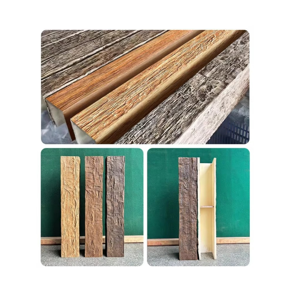
Aluminum channel inserts provide effective internal stiffening without excessive weight. Standard extruded channels—typically 2x3 or 3x4 inch—install into beam interiors running full length. The aluminum provides bending stiffness that polyurethane foam cannot, dramatically increasing allowable spans. Installation requires fabricating beams with internal mounting provisions or retrofitting existing beams by opening one face, inserting channel, and resealing.
Wood or composite lumber cores create even greater stiffness than aluminum but add weight that must be accounted in ceiling attachment design. A 2x4 or 2x6 lumber core running beam length essentially creates a solid-beam hybrid—the core provides structural stiffness while polyurethane shell delivers aesthetic appearance. This approach works well for new fabrication but retrofits prove challenging given the construction required to integrate cores into hollow beams.
Steel rod or cable tensioning systems use principles from concrete post-tensioning—steel elements run through beam interiors with end anchorages creating compression forces that counteract deflection. These systems require engineering design and careful installation but can enable spans that would otherwise be impossible. The complexity and cost typically justify only in situations where alternative solutions prove unworkable.
Fiberglass rod reinforcement offers excellent stiffness-to-weight ratio suitable for long spans. Pultruded fiberglass rods—available in various diameters—install similarly to aluminum channels but with lighter weight. The material won't rust, doesn't conduct electricity (important near light fixtures), and provides high tensile strength. Cost typically exceeds aluminum but weight savings may justify premium in difficult-access installations.
External Support Systems and Concealment Strategies
Decorative brackets at intermediate positions provide authentic-appearing support while actually constraining beam deflection. These brackets—whether timber corbels, metal straps, or carved supports—attach to walls with beams bearing on bracket tops. The brackets serve both decorative and structural functions, reducing unsupported spans to acceptable lengths while appearing as intentional design elements.
Ceiling-mounted posts or columns create vertical support where beams cross open spaces without walls for bracket mounting. These elements might be decorative timber posts, metal pipe legs, or composite columns that appear structural even when they're purely functional. Positioning posts at furniture groupings or architectural features makes them appear intentional rather than improvised solutions to span problems.
Cable or rod suspension from structure above provides nearly-invisible support when concealment proves critical. Aircraft cable or threaded rod drops from ceiling joists or structure, connecting to beam interiors through small penetrations in beam tops. Painted to match ceilings or beams, these supports virtually disappear while preventing sag. The support points must fasten to adequate structure—drywall alone cannot support suspension loads.
Hidden mounting blocks increase effective attachment frequency without visible fasteners. These blocks—attached to ceiling structure between adhesive-mounted beam and ceiling surface—provide intermediate support points contacted by beam during installation. The blocks support beam weight at intervals preventing sag while remaining invisible from below since beams conceal them entirely.
Installation Techniques for Long-Span Applications
Pre-cambering compensates for expected deflection by installing beams with intentional upward bow. When installed beam center sits 1/2 inch high, subsequent deflection brings it to level position rather than sagging below. This technique requires predicting deflection accurately—too much camber leaves permanent upward bow, too little allows visible sag. It works best when combined with reinforcement preventing excessive long-term creep beyond predicted deflection.
Adhesive application patterns for long spans require continuous coverage rather than intermittent beads. Spot adhesive application cannot prevent sag—continuous adhesive creates broad distribution preventing beam from pulling away from ceiling as it deflects. Use high-strength construction adhesive rated for sustained loading, not general-purpose adhesive adequate for short spans but insufficient for long applications.
Mechanical fastener schedules must increase frequency in long spans. Where 24-inch spacing suffices for 12-foot beams, 16 or 12-inch spacing may be necessary for 20+ foot spans. Calculate fastener requirements based on beam weight, span length, and attachment substrate strength. Each fastener must engage structural framing—ceiling substrate alone cannot provide adequate support.
Temporary support during adhesive cure proves essential for long spans. Props, braces, or temporary fasteners maintain beam position through initial cure when adhesive hasn't achieved full strength. Removing temporary supports prematurely allows sagging during cure that subsequent adhesive strength cannot correct. Maintain support 72-96 hours ensuring complete cure before trusting installation to support itself.
Load Considerations Beyond Self-Weight
Lighting fixture loads add weight that span calculations must account for. A 15-pound chandelier suspended from beam center adds substantially to deflection-causing loads. Multiple fixtures along beam length compound effects. When planning fixture integration, either reinforce beams anticipating fixture loads or support fixtures independently from structure above rather than trusting beams to carry them.
Hanging décor—plants, banners, seasonal decorations—creates loads homeowners add after installation without considering beam capacity. Client education about load limitations prevents well-intentioned decoration from causing sag problems. Provide weight guidelines or recommend alternative hanging strategies using structure behind beams rather than beams themselves.
Snow loads in covered outdoor applications where open beam ends admit snow accumulation can create unexpected loading. A partially-open porch might accumulate several inches of snow on beam tops—weight that indoor installations never face. Either design these installations with greater conservatism or ensure beam ends remain fully protected preventing snow accumulation.
Maintenance access loads when workers step on or hang from beams during ceiling maintenance create impact and concentrated loads exceeding design assumptions. While beams shouldn't design for misuse, considering that someone might eventually climb into the ceiling space and contact beams suggests conservative design practices preventing damage from foreseeable misuse.
Repair and Remediation of Sagging Installations
Assessment of sagging determines whether the problem stems from inadequate support, adhesive failure, material degradation, or excessive span. Visual inspection, deflection measurement, and adhesive bond testing reveal root causes guiding appropriate corrections. Treating symptoms without addressing causes leads to recurring problems—understand why sagging occurred before implementing fixes.
Adhesive reapplication cannot correct sag once established—removing and reinstalling beams with proper reinforcement proves necessary. Attempting to force-straighten sagged beams risks material damage and won't address underlying insufficient support. Accept that correcting sag requires removal and proper reinstallation rather than seeking shortcuts that won't deliver lasting results.
Reinforcement insertion during repair follows strategies described earlier but with added complication of working with existing finished beams. Opening one beam face, inserting reinforcement, and resealing requires careful workmanship maintaining appearance. This remedial work typically costs 150-200% of what proper installation would have cost initially—strong incentive to get installations right the first time.
Client communication about repairs should emphasize that sagging indicates installation exceeded product capabilities, not product defect. Managing expectations and explaining that corrections implement solutions that should have been incorporated initially helps maintain relationships during what's inherently an awkward situation where original installation fell short.
Documentation and Quality Assurance
Installation records documenting span lengths, reinforcement details, and support strategies create references for warranty administration and future maintenance. When sagging occurs, these records prove whether installation followed specifications or deviated in ways that voided recommended practices. Both installers and clients benefit from documentation that clarifies responsibilities.
Periodic inspection schedules for long-span installations—perhaps annually for first three years—identify developing sag before it becomes severe. Early intervention when deflection reaches 1/4 inch proves far simpler than waiting until multiple inches of sag demand complete remediation. This proactive monitoring represents professional practice that prevents small problems from becoming large failures.
Manufacturer warranties typically exclude installations exceeding span recommendations or lacking specified support—understanding coverage limitations prevents disputes. When engineering decisions push beyond standard practices, document the rationale and client acceptance of associated risks. This transparency protects professionals from liability when calculated risks don't deliver hoped-for results.

Long unsupported beam spans create engineering challenges that aesthetic preferences and budget constraints cannot wish away. Physics determines beam behavior, and installations ignoring span limitations face eventual sagging that no amount of careful workmanship prevents. When project requirements demand extended spans, proper reinforcement and support strategies enable successful installations—but only when implemented thoughtfully during original construction. The modest incremental cost of proper engineering proves invariably less expensive than remedial corrections after installations fail, making conservative design practices and adherence to span recommendations sound business practice protecting both performance and professional reputation.
Technical References
ASTM standards cited in every specification
Test Data
Lab results from internal testing program
Updated 2026
Reviewed against current product specs