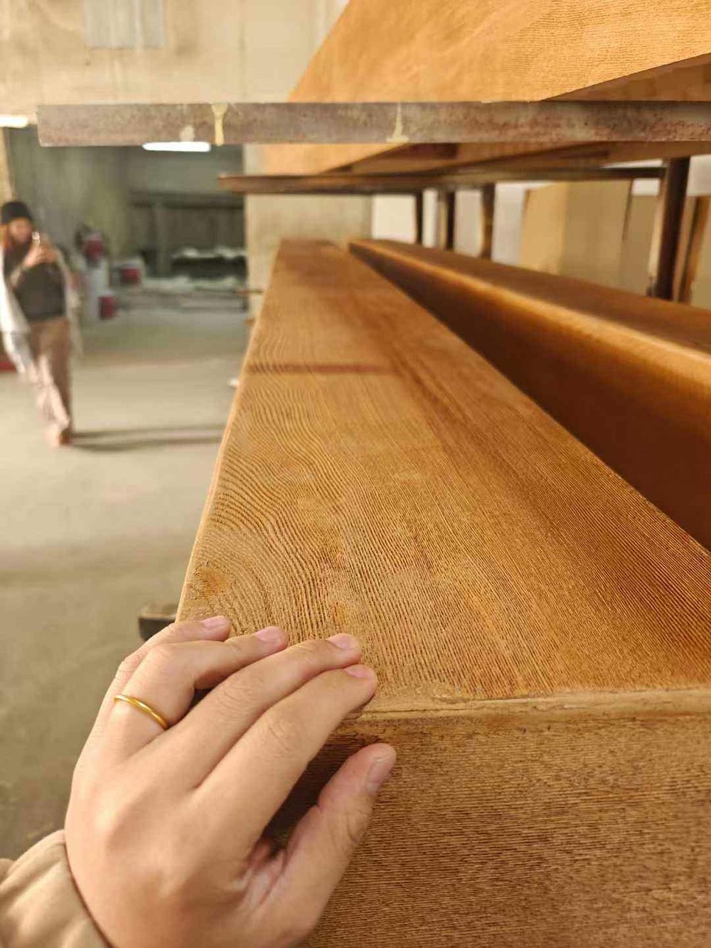
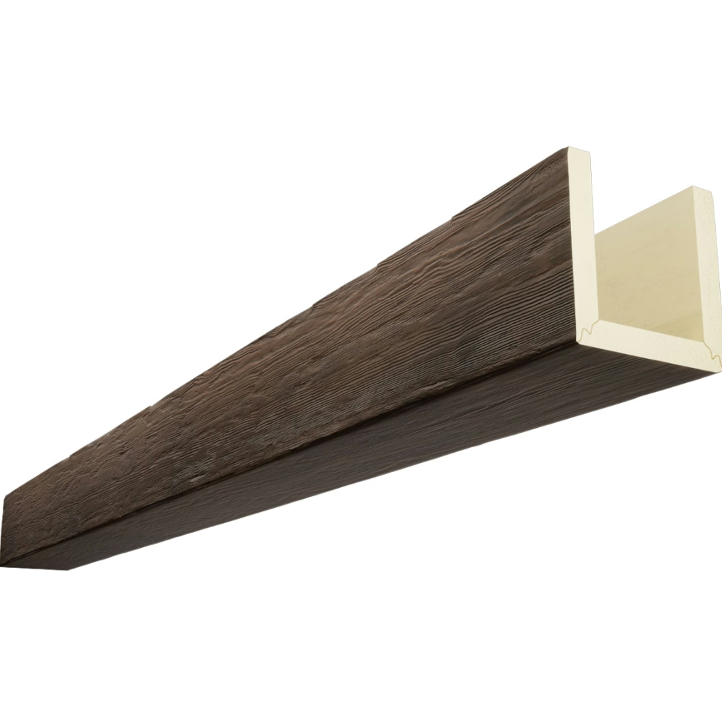
The great room stretched before me with a soaring 24-foot cathedral ceiling—magnificent volume that felt somehow empty and directionless. The architect's original design specified no ceiling treatment, leaving the vast plane of drywall feeling more like an unfinished warehouse than a luxury home. When I proposed adding beams, the client immediately asked the question that determines success or failure: "How many beams, and where do they go?" That question launches the critical design work that separates compelling ceiling treatments from arbitrary additions that never quite look intentional.
Cathedral and vaulted ceilings present unique design challenges. Their dramatic height and angled planes create visual power, but that same scale can feel overwhelming without elements establishing human-scaled reference and architectural rhythm. Understanding layout principles, spacing guidelines, and proportion relationships allows designers to create beam arrangements that enhance rather than fight the architectural geometry these ceilings present.
Understanding Ceiling Geometry and Sight Lines
Cathedral ceilings typically follow roof slopes from low points at exterior walls up to ridge peaks at room centers. This symmetrical geometry creates a powerful axis along the ridge line that should inform beam layout decisions. Beams can run parallel to the ridge—emphasizing the long axis—or perpendicular across the slope—breaking the span and creating rhythm across the shorter dimension.
The viewing experience changes fundamentally with ceiling height. In conventional 8-10 foot spaces, you see ceiling details at acute angles from below. In cathedral spaces reaching 20-30 feet, sight lines become more horizontal, allowing you to see beam faces and profiles that would appear foreshortened in shorter rooms. This visibility shift means beam dimensions and spacing that would appear appropriate in normal-height rooms often read as inadequate in tall vaulted spaces.
Multiple viewing positions within a room require considering beam appearance from various locations. Standing at room entry, at the seating area, looking back from the fireplace—each position presents different perspectives on the beam arrangement. Layouts that look balanced from one viewpoint may appear awkward from others. Good design accounts for these varied perspectives, creating arrangements that work from the primary sight lines while remaining acceptable from secondary positions.
Natural light behavior in cathedral spaces affects how beams appear throughout the day. Tall windows typical of these rooms admit light at steep angles that create strong shadows from projecting beams. Morning and evening light raking across beam faces emphasizes texture and dimensionality. Midday overhead light flattens appearance, making spacing and proportion more critical to visual interest. Consider how beam shadows will fall during peak room use times—dinner hour in dining rooms, morning in kitchens, evening in living rooms.
Parallel Beam Layouts: Running with the Ridge
Beams running parallel to the ridge line—along the room's long axis—emphasize length and create strong directional pull. This layout works particularly well in rectangular rooms where you want to reinforce the primary axis, drawing eyes from entry toward a focal point like a fireplace or view window at the far end. The parallel beams act as visual arrows directing attention longitudinally through the space.
Spacing for parallel beam layouts traditionally references structural beam spacing in timber frame construction—typically 4 to 8 feet between members. This range provides architectural authenticity while allowing practical variation to accommodate room width and desired visual density. Wider spacing creates clean, minimalist effect with strong individual beam presence. Tighter spacing builds visual rhythm and warmth appropriate to traditional or rustic design intent.
The calculation method for determining beam count starts with room width divided by desired spacing, then adjusting for practical and visual considerations. A 20-foot-wide room divided by 6-foot spacing suggests 3-4 beams. You might round to 3 beams evenly spaced, or add a fourth to increase rhythm. Avoid layouts that place beams too near side walls—typically maintain at least 2-3 feet from walls to perimeter beams, preventing the "cage" effect that occurs when beams frame the ceiling perimeter.
Beam sizing for parallel layouts should relate to both spacing and room scale. Tight 4-foot spacing can accept smaller 6x6 or 6x8 inch beams without looking spindly. Wide 8-foot spacing in large rooms may require 8x10 or even 10x12 inch beams to maintain visual presence and prevent the floating, disconnected appearance undersized beams create. The beam cross-section should feel substantial relative to the spacing it spans.
Edge conditions where parallel beams meet end walls require resolution. Beams can terminate against walls in several ways: stopping short of the wall with a reveal gap, running into the wall to suggest continuation beyond, or connecting to decorative brackets or corbels that provide visual support. The choice depends on design style—modern designs favor clean reveals, traditional styles often incorporate brackets suggesting structural function.
Perpendicular Beam Layouts: Spanning the Slope
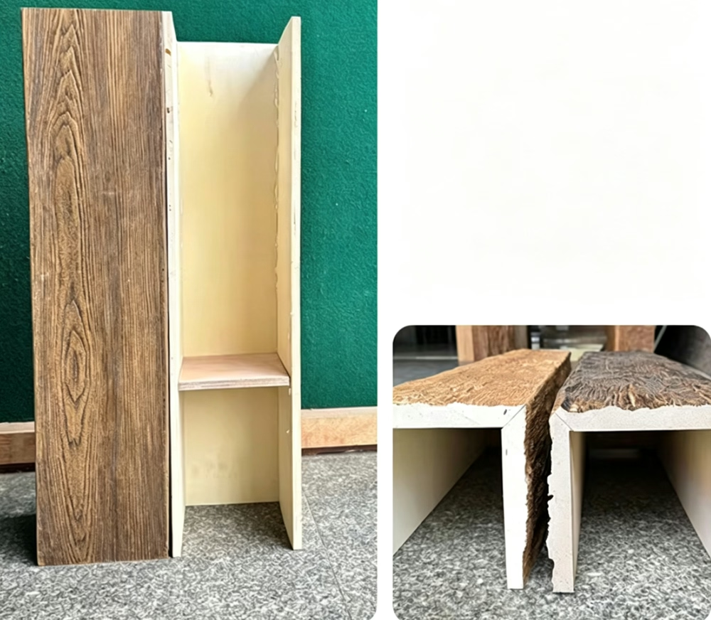
Beams running perpendicular to the ridge—across the cathedral slope—create a different spatial effect, breaking the long span into segments and establishing horizontal rhythm that counters the vertical thrust of the tall space. This layout reads as more structurally authentic since actual timber rafters span this way, supporting roof loads by transferring them down to exterior walls.
The spacing calculation for perpendicular beams follows similar structural precedents, typically 3-6 feet on-center to replicate rafter spacing in timber frame construction. This closer spacing compared to parallel beam layouts reflects the difference between structural joists (spanning short distances) and ridge beams (spanning long distances). The tighter rhythm creates richer texture and more comprehensive ceiling coverage than parallel layouts typically achieve.
Visual balance in perpendicular layouts demands careful placement relative to room geometry. The symmetry of cathedral ceilings suggests symmetrical beam spacing, with equal distances from ridge to first beam, between all intermediate beams, and from last beam to wall. Slight variations that respond to lighting fixtures, architectural features, or spatial subdivisions can work if they appear intentional rather than accidental.
Beam sizing in perpendicular layouts can often be smaller than parallel applications since the tighter spacing creates more visual fill. Where parallel 8-foot spacing might require 10x12 beams, perpendicular 4-foot spacing might achieve similar effect with 6x8 or 8x8 beams. The increased quantity compensates for reduced individual size, while lighter beams appear more appropriate to the rafter-like spanning direction they replicate.
The ridge intersection proves critical in perpendicular layouts. Beams can stop just short of the ridge, allowing the peak line to read continuously, or they can connect at the ridge, meeting opposing slope beams in a centered joint. Some designs incorporate a ridge beam—a heavier member running along the peak—that perpendicular beams appear to frame into, creating hierarchical organization that clarifies the structural logic the decorative system suggests.
Grid and Coffered Layouts: Combined Directions
Grid layouts combine parallel and perpendicular beams, creating recessed panels or coffers between crossing members. This sophisticated approach builds the richest visual texture and works particularly well in large formal spaces where simple one-directional layouts might feel incomplete. The grid organization clarifies room geometry while creating shadowed depth that adds architectural gravitas.
The spacing module for grid layouts must work in both directions—often resulting in square or nearly-square panels rather than highly rectangular ones. A room that's 20 feet wide by 30 feet long might use a 5-foot module creating a 4x6 grid of coffers, or a 6-foot module yielding roughly 3x5 coffers. Perfect squares aren't necessary, but extreme rectangles—like 3x9 foot panels—look awkward and undermine the organizational clarity grids should provide.
Beam sizing in grids requires hierarchy to prevent visual confusion. Primary beams—usually those running parallel to the ridge or along the room's longer axis—should be larger than secondary cross beams. This size difference clarifies the structural logic and creates visual order. Typical hierarchies might pair 8x10 primary beams with 6x8 secondary members, or 10x12 primary with 8x8 secondary beams.
The increased complexity of grid layouts demands more careful planning of lighting, HVAC, and other ceiling-mounted systems. Recessed lights might center in coffers, nestle alongside beams, or mount within beam faces. Supply and return air registers must coordinate with the grid module to avoid awkwardly straddling beams or disrupting the panel rhythm. This coordination should occur during design development, not as a field improvisation when conflicts appear during installation.
Installation sequencing for grids typically proceeds in layers—primary beams first, establishing the major organizational lines, then secondary beams installing between primaries to complete the grid. This sequence allows adjusting spacing if field dimensions vary from plans, with flexibility built into the secondary beam positioning that would be impossible if all beams were committed simultaneously.
Proportion Guidelines and Scale Relationships
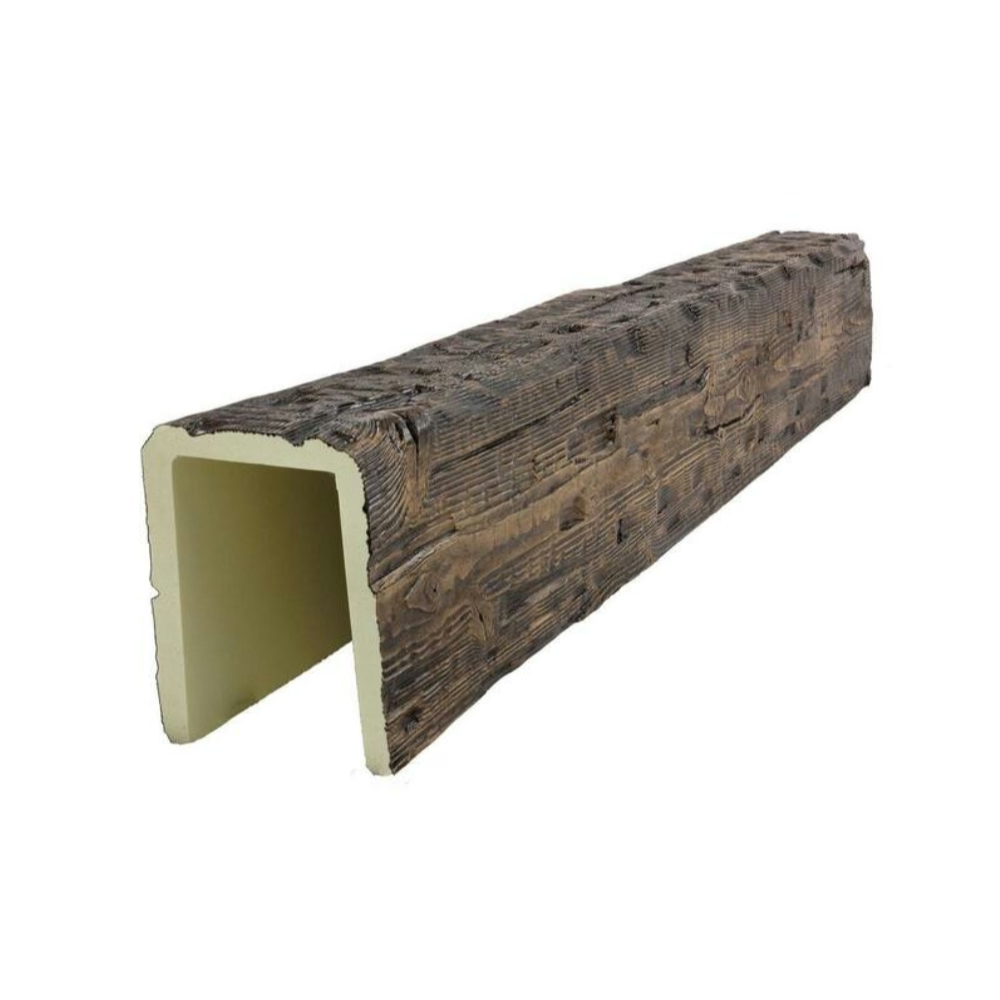
The relationship between beam dimensions and spacing follows proportional guidelines that create visual balance. A general rule suggests that spacing should be 6-12 times the beam height. An 8-inch-tall beam looks appropriately scaled at 4-8 foot spacing, while a 12-inch beam works at 6-10 foot spacing. Tighter spacing can appear busy unless design intent specifically targets dense timber-frame character. Wider spacing risks beams appearing to float without structural logic connecting them.
Ceiling height relative to beam size follows similar proportional thinking. Low cathedral ceilings—12-16 feet at the peak—should use smaller beam profiles (6x6, 6x8) to avoid overwhelming the space. Medium cathedral heights of 18-24 feet accommodate standard residential sizes (8x8, 8x10) comfortably. Tall cathedrals exceeding 24 feet need commercial-scale beams (10x12, 12x14) to maintain visual presence at those distances.
Room dimensions relative to beam quantity prevent both under and over-treatment. Small cathedral spaces—12x16 foot rooms—might need only 2-3 beams to avoid cluttering the ceiling. Medium rooms of 16x24 feet typically handle 3-5 beams well depending on layout direction. Large great rooms exceeding 20x30 feet can accommodate 5-8 or more beams, particularly in grid layouts where quantity creates the design intent.
The visual weight balance between ceiling treatment and other room elements prevents beams from dominating spaces inappropriately. Rooms with substantial millwork, built-ins, or architectural features can accept bolder beam treatments since they're part of an overall composition with visual complexity. Minimalist rooms with limited architectural detail might require more restrained beam approaches—fewer, cleaner beams that add interest without overwhelming the simplicity other design decisions establish.
Special Conditions and Problem Solving
Asymmetrical ceiling geometries—common in additions or renovated spaces—challenge the symmetrical layouts that feel natural in purpose-built cathedral ceilings. These situations may require abandoning pure symmetry in favor of layouts that respond to actual room geometry while maintaining visual balance through other means—perhaps irregular spacing that relates to functional zones rather than mathematical division of overall dimensions.
Lighting fixture integration fundamentally affects beam layout. Chandeliers, pendant clusters, or ceiling fans occupy specific positions that beam layouts must acknowledge. Beams might frame around these fixtures, creating emphasized ceiling zones that highlight the fixture importance. Alternatively, fixtures might mount within beam faces or between beams in ways that integrate lighting and structure as unified composition rather than conflicting systems.
Structural realities sometimes constrain beam positions—actual ceiling joists, HVAC chases, or structural members may occupy specific locations where mounting beams proves easier than alternative positions. While decorative beams theoretically can go anywhere, practical installation often works better when beam layouts align with underlying structure providing solid attachment points. Good design accommodates these practical constraints within overall aesthetic organization.
The relationship between sloped and flat ceiling sections—common in cathedral rooms with flat-ceilinged perimeter zones—requires transition details. Beams might run continuously from sloped to flat sections, stepping down to follow ceiling geometry. Or layouts might treat each ceiling plane independently, with beams on the cathedral section not extending onto perimeter flat ceilings. The choice depends on space size and how unified or differentiated you want these zones to feel.

Cathedral ceiling beam layout design synthesizes architectural understanding, proportional thinking, and practical constraints into arrangements that feel both intentional and inevitable—as though the beams belong exactly where they sit. This design sophistication separates professional results from amateur attempts that add beams without the underlying logic that makes architecture compelling. The layout question isn't about following formulas but understanding principles that guide toward solutions unique to each space's geometry, scale, and design intent.
Technical References
ASTM standards cited in every specification
Test Data
Lab results from internal testing program
Updated 2026
Reviewed against current product specs