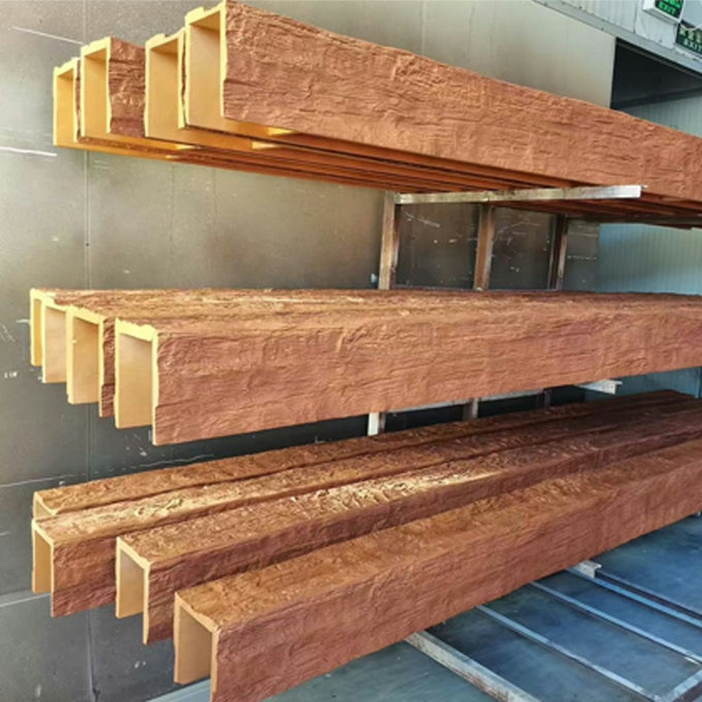
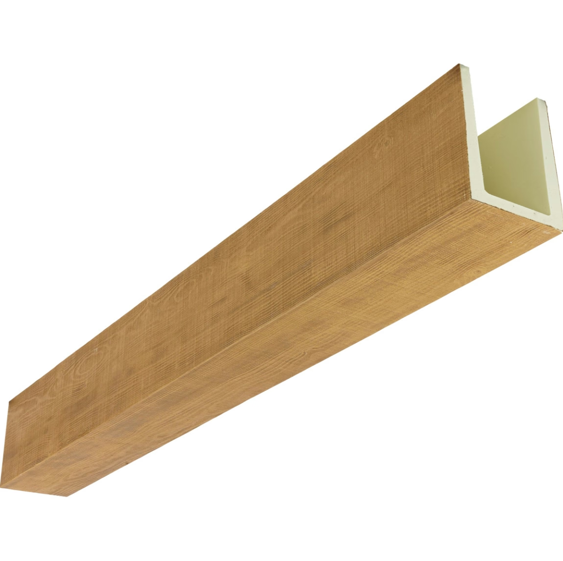
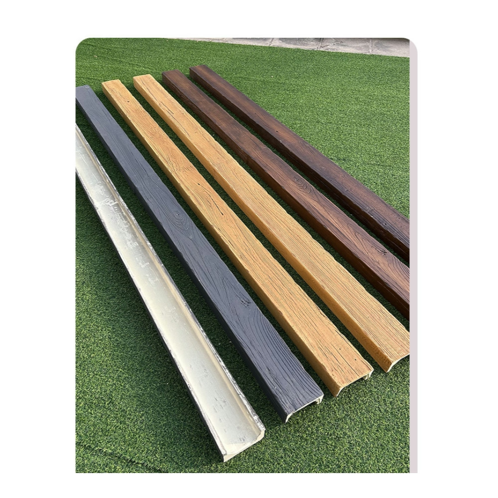
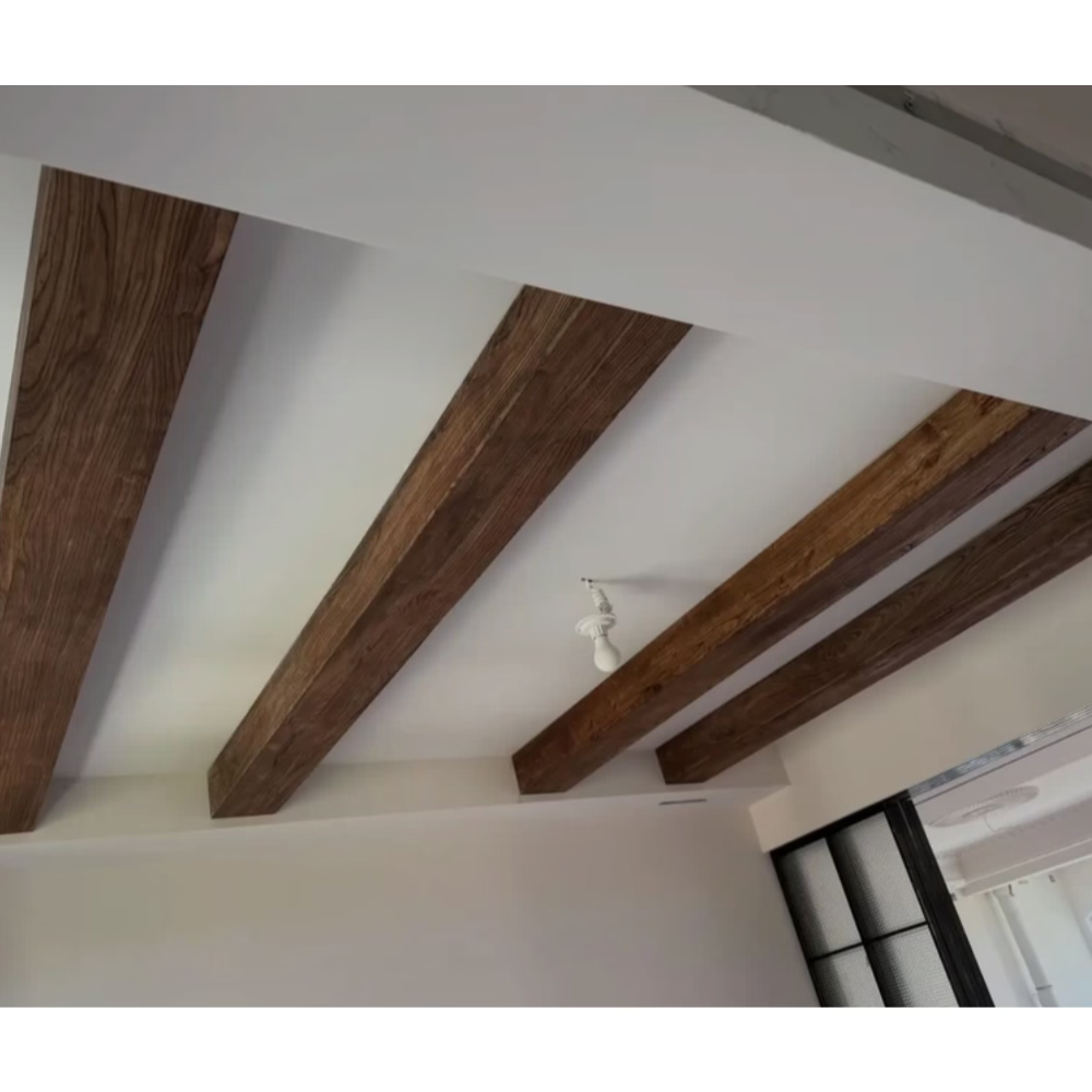
The mountain home featured dramatic cathedral ceilings with exposed beams creating stunning interior volume. Energy audit one year post-construction revealed disappointing thermal performance—infrared imaging showed cold spots throughout ceiling corresponding precisely to beam mounting blocking locations. The blocking—2×6 wood running perpendicular to rafters supporting beam attachments—created continuous thermal bridges through the insulated rafter bays. Combined with inadequate air sealing around blocking, these penetrations degraded ceiling R-value from design R-49 to measured effective R-28 at blocking locations. Heat loss through thermal bridges added $800 annually to heating costs while ice dams formed above blocking where heat loss melted snow. We retrofitted by adding rigid foam insulation between blocking and interior finish, improving air sealing, and installing heat cables managing ice dams. That $12,000 remediation taught me that decorative beam installations demand building science rigor equal to structural and aesthetic considerations—thermal performance directly affects comfort and operating costs.
Cathedral ceiling insulation strategies around decorative beam blocking require understanding heat flow physics, thermal bridge mechanics, and insulation/air sealing details ensuring continuous thermal envelopes despite structural penetrations for beam mounting systems. Proper detailing maintains design thermal performance while accommodating beam installation requirements.
Understanding Cathedral Ceiling Thermal Challenges
Heat flow physics in cathedral ceilings creates challenging conditions since warm interior air directly contacts insulated roof assemblies without attic buffer spaces. Flat ceiling attics allow thick insulation with minimal thermal bridging through framing. Cathedral ceilings constrain insulation to rafter depth while rafters create unavoidable thermal bridges. Understanding these fundamental differences guides appropriate cathedral ceiling strategies.
Thermal bridging through framing members where wood rafters create conductive paths through insulation reduces effective R-value below nominal insulation values. Solid wood rafters with R-1.25 per inch conduct heat far more than fiberglass insulation at R-3.5 per inch. Rafters occupying 10-15% of ceiling area can reduce overall assembly R-value by 20-30% through thermal bridging. Additional blocking for beams compounds this bridging creating even greater heat loss.
Convection loops within rafter bays where air circulates between warm interior and cold roof sheathing via gaps in insulation transfers substantial heat. Preventing convection requires complete insulation fill without gaps or voids. However, beam blocking installations often create voids where insulation doesn't completely fill spaces around blocking.
Condensation risks in cold climates occur when warm humid interior air reaches cold surfaces within assemblies dropping below dewpoint temperature. Proper vapor control and insulation preventing warm air reaching cold zones eliminates condensation. However, thermal bridges cooling interior surface areas below dewpoint create localized condensation even when bulk assembly performs adequately.
Stack effect in multi-story spaces with cathedral ceilings creates strong buoyancy-driven air movement where warm air rises through any available leakage paths. This natural convection amplifies air leakage impacts in tall cathedral spaces compared to standard ceiling heights. Excellent air sealing proves particularly critical in cathedral ceiling applications.
Beam Blocking Thermal Bridge Analysis
Continuous wood blocking running perpendicular to rafters creates worst-case thermal bridging. Unlike individual rafters with insulated spaces between, continuous blocking provides uninterrupted conductive path through entire ceiling assembly. A 1.5-inch × 5.5-inch blocking member (typical 2×6) creates approximately 0.6 square feet of thermal bridge per linear foot—substantial heat loss pathway.
Quantifying thermal bridge effects using parallel-path calculation methods (ASHRAE method) or thermal modeling software reveals actual performance degradation. Simple calculation: if rafter bays provide R-38 insulation but blocking areas show R-7 (R-1.25/inch × 5.5 inches), then 10% blocking area reduces average assembly R-value to approximately R-32—16% performance reduction. Actual performance might prove worse if air leakage compounds thermal bridging.
Thermal imaging visualization using infrared cameras during cold weather dramatically reveals thermal bridge patterns. Cold spots appearing in regular patterns corresponding to blocking locations confirm thermal bridge problems. Thermal imaging provides diagnostic confirmation and helps prioritizing remediation efforts.
Energy cost implications from thermal bridging can total hundreds or thousands of dollars annually depending on climate, energy costs, and ceiling area. Calculating energy penalties from thermal bridges quantifies economic impacts justifying insulation improvement investments. Even modest thermal bridge mitigation often pays back through energy savings within 3-5 years.
Ice dam formation risks where heat loss through thermal bridges melts snow on roof surfaces which refreezes at eaves creating ice dams. Ice dams damage roofing, create leaks, and indicate wasted heating energy. Eliminating thermal bridges preventing snow melt eliminates ice dam risks while improving energy efficiency.

Insulation Strategies for New Construction
Raised heel trusses or energy trusses incorporating raised heels at eaves allow full-depth insulation extending to exterior walls without compression. Standard trusses force insulation compression at eaves reducing R-value where it matters most. Energy trusses cost 10-15% more than standard but deliver substantially better thermal performance. When incorporating beam blocking, energy trusses provide additional depth accommodating blocking without compromising insulation.
Continuous exterior insulation over roof sheathing breaks thermal bridges through rafters and blocking by placing insulation layer outside structural framing. Perhaps 2-4 inches polyisocyanurate or XPS over sheathing, followed by additional rafter bay insulation, achieves high R-values while eliminating framing thermal bridges. Exterior insulation adds cost and construction complexity but delivers superior thermal performance particularly in very cold climates.
Spray foam insulation in rafter bays creates air seal and insulation in single application while conforming around blocking and irregular framing. Closed-cell spray foam provides excellent air sealing, moisture resistance, and R-6.5+ per inch allowing high R-values in limited depths. However, spray foam costs 2-3× fiberglass while creating vapor barrier potentially problematic in some climates. Open-cell foam at R-3.5/inch provides air sealing at lower cost but requires vapor retarder and doesn't provide moisture resistance.
Rigid foam between blocking and interior finish creates thermal break reducing blocking thermal bridge impacts. Installing 1-2 inches rigid foam over blocking before mounting beams adds R-5 to R-10 at blocking locations dramatically reducing thermal bridge severity. This simple detail adds modest cost while providing substantial thermal benefit.
Staggered or offset blocking designing blocking systems avoiding continuous thermal bridges reduces bridging impacts. Perhaps staggering 2-foot blocking sections with 4-foot gaps allows insulation continuity while still providing beam mounting support. This approach requires engineering coordination ensuring adequate beam support while optimizing thermal performance.
Retrofit Insulation Strategies
Interior rigid foam application over existing ceilings including over blocking before installing beams improves thermal performance in retrofits where exterior approaches prove impractical. Perhaps 1-1.5 inches foil-faced polyisocyanurate adds R-6 to R-9 while creating thermal break over blocking. However, interior insulation reduces ceiling height and requires extending electrical boxes and other penetrations.
Blown-in dense-pack cellulose or fiberglass in accessible rafter bays increases insulation levels in under-insulated cathedral ceilings. Dense-pack insulation achieves better performance than loose-fill by eliminating convection while conforming around obstructions. However, dense-pack installation requires access for blowing equipment potentially limiting retrofit applications.
Spray foam retrofit injecting foam into closed rafter bays through small access holes provides comprehensive insulation and air sealing without removing interior finishes. Injection foam typically uses slow-rise low-pressure formulations preventing pressure damage to finishes. This expensive but minimally disruptive approach suits occupied buildings where major demolition proves unacceptable.
Exterior overcoating adding continuous insulation over existing roof systems when re-roofing provides opportunity for thermal bridge mitigation. Combining re-roofing with energy improvements leverages construction mobilization across multiple objectives. However, exterior insulation requires raising roof height impacting roof-wall transitions, eaves details, and possibly requiring building permit review.

Air Sealing Critical Details
Blocking-to-rafter junctions where blocking intersects rafters create three-dimensional geometry with cracks and gaps allowing air leakage. Spray foam, caulk, or gaskets sealing these junctions prevents air infiltrating insulated cavities. Even small gaps create significant air leakage degrading thermal performance and creating condensation risks.
Drywall-to-blocking interface where ceiling finish meets blocking requires continuous air seal preventing interior air accessing insulated cavities. Acoustic sealant, gaskets, or specialized air-sealing tapes creates durable seals. Standard drywall installation without deliberate air sealing often leaves gaps particularly where blocking creates irregular surfaces.
Penetrations through blocking for electrical wiring, lighting, or other building systems require air sealing each penetration. Foam sealant, putty pads, or purpose-built seals close penetrations maintaining air barrier continuity. Unsealed electrical penetrations represent major air leakage sources undermining insulation effectiveness.
Vapor barrier continuity in cold climates requiring interior vapor barriers demands connecting ceiling vapor barriers to blocking and beam mounting systems without gaps. Tape or adhesive joining vapor barrier sheets to framing, sealed penetrations, and continuous barrier planes creates effective moisture control. Discontinuous vapor barriers allow moisture migration into cold assemblies risking condensation.
Testing and verification using blower door testing quantifies air leakage revealing whether air sealing achieved targets. Infrared thermography during blower door depressurization visualizes leakage locations enabling targeted sealing improvements. Testing should occur after insulation/air sealing completion but before finishes conceal work enabling corrections while access remains good.
Ventilation Considerations
Ventilated cathedral ceilings maintaining air space between insulation and roof sheathing prevents moisture accumulation in assemblies. Ventilation requires continuous air path from soffit to ridge vents—typically 1.5-2 inch ventilation space. However, ventilated designs sacrifice insulation depth to ventilation space limiting achievable R-values in standard rafter depths.
Unventilated (hot roof) cathedral ceilings eliminating ventilation allows full rafter depth for insulation achieving higher R-values in limited depths. Unventilated assemblies require excellent air sealing and either impermeable insulation (closed-cell foam) or vapor barriers preventing moisture accumulation. Building codes and manufacturers provide specific requirements for unventilated assemblies varying by climate.
Proper ventilation design when using ventilated approach requires maintaining unobstructed airflow throughout ceiling despite blocking and beam mounting systems. Ventilation baffles, chutes, or blocking designs avoiding airflow restriction maintains ventilation effectiveness. Poorly detailed ventilation systems failing to maintain airflow offer worst-of-both-worlds—sacrificed insulation depth without ventilation benefits.
Climate-Specific Strategies
Cold climate priorities (Zones 6-8) emphasize thermal resistance and inward vapor control preventing interior moisture reaching cold surfaces. Perhaps R-49+ cathedral ceilings using combination of cavity insulation plus continuous exterior insulation. Interior vapor barriers (6-mil polyethylene or vapor-retarding primer) and excellent air sealing prove essential.
Mixed climate approaches (Zones 4-5) balance heating and cooling needs often using moderate R-values (R-30 to R-38) with vapor management allowing seasonal drying both directions. Smart vapor retarders adapting permeability to seasonal conditions work well. Moderate insulation levels without excessive vapor barrier impermeability prevents moisture trapping while providing adequate thermal performance.
Hot climate strategies (Zones 1-3) prioritize solar heat rejection and cooling load reduction. Radiant barriers on roof sheathing, moderate insulation (R-20 to R-30), and vapor-open assemblies allowing drying outward prove appropriate. In cooling climates, moisture drive occurs from exterior inward requiring different vapor management than cold climates.
Building Code Compliance
International Energy Conservation Code (IECC) prescriptive requirements specify minimum ceiling R-values by climate zone—perhaps R-38 in Zone 4, R-49 in Zone 6. Cathedral ceilings must meet these minimums despite framing depth limitations. Demonstrating code compliance requires accounting for thermal bridges using approved calculation methods.
Performance path compliance through whole-building energy modeling enables demonstrating code compliance through overall building performance rather than prescriptive component requirements. This flexibility allows optimizing across building systems—perhaps accepting slightly reduced ceiling R-values if superior walls and windows deliver equivalent overall performance.
Inspection requirements including insulation grade certification (Grade I, II, or III) and air sealing verification ensure installation quality. Grade I insulation (no voids, complete fill, proper installation) provides rated performance while lower grades show reduced effectiveness. Inspections should occur before finish installation while corrections remain practical.
Cost-Benefit Analysis
Incremental insulation costs for improved details might add $2-5 per square foot to cathedral ceiling assemblies. However, energy savings might total $0.50-1.50 per square foot annually depending on climate and energy costs. Simple payback periods of 3-7 years make improved insulation economically rational beyond just code compliance.
Comfort improvements from eliminating cold spots and drafts provide value difficult quantifying financially but representing real quality-of-life benefits. Occupants consistently rate uniform comfortable temperatures as high-value feature—worth premium beyond just energy cost savings.
Durability improvements from proper moisture management preventing condensation-induced damage provides long-term value. Moisture problems create mold, rot, and structural degradation—expensive problems that proper building science prevents. Considering lifecycle costs rather than just first costs reveals true value of quality assemblies.
Professional Building Science Integration
Cathedral ceiling insulation strategies around decorative beam blocking require understanding thermal bridge physics, implementing comprehensive air sealing, and coordinating building systems achieving high-performance assemblies. Decorative beam installations shouldn't compromise thermal performance—proper detailing achieves both aesthetic and thermal objectives. For builders, architects, and contractors creating cathedral ceiling spaces, applying building science principles alongside structural and aesthetic considerations delivers energy-efficient comfortable buildings minimizing operating costs and environmental impacts.
The discipline to detail thermal bridges, specify appropriate insulation assemblies, and verify performance through testing distinguishes professional practice from casual approaches ignoring thermal performance. Building science application represents fundamental responsibility that quality construction demands.
通过系统的保温设计和热桥缓解策略,可以确保大教堂式吊顶在安装装饰梁的同时,保持优异的热工性能和能源效率。
Technical References
ASTM standards cited in every specification
Test Data
Lab results from internal testing program
Updated 2026
Reviewed against current product specs