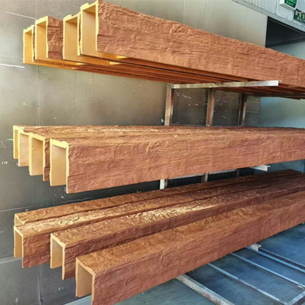
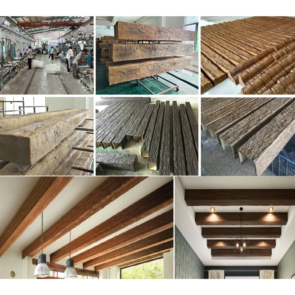
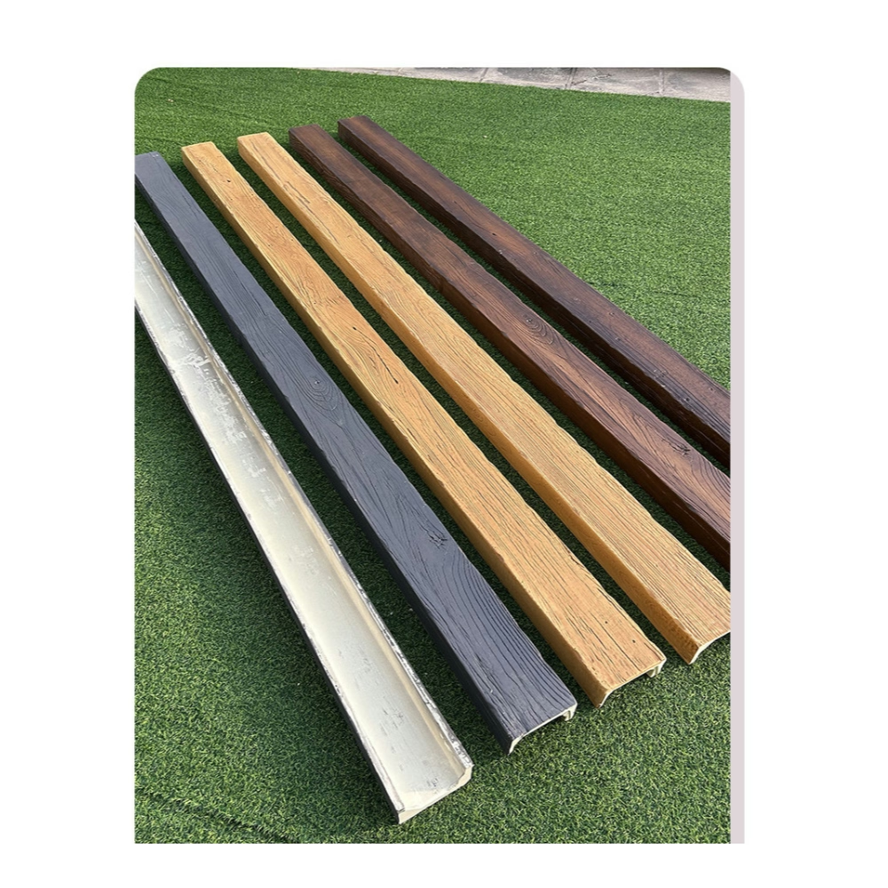
The energy consultant performing thermal modeling for a net-zero energy office building identified unexpected heat loss that degraded the building's projected performance by 8%: the ceiling beam blocking specified in construction documents created thermal bridges that interrupted the continuous insulation layer at forty-eight locations throughout the exposed ceiling areas. Each beam attachment point used solid wood blocking extending from structure through the insulation layer to provide fastening for decorative beams below. These thermal bridges—totaling less than 1% of ceiling area—created disproportionate energy loss because the highly conductive wood blocking short-circuited insulation that otherwise achieved R-38 performance. The consultant recommended revised blocking details using insulated standoffs that supported beams while maintaining continuous insulation integrity. Implementing the revision during design cost $2,400 in additional materials. Discovering the thermal bridging issue after construction would have meant accepting permanent building performance degradation or expensive retrofit work to address installed conditions.
Continuous insulation thermal bridge mitigation at ceiling beam blocking addresses a building science challenge that energy codes increasingly emphasize. Modern building energy standards recognize that overall envelope thermal performance depends not just on insulation R-value in typical assemblies but also on continuity—whether the insulation layer remains uninterrupted by conductive elements that create thermal bypass paths. Ceiling beam attachment blocking represents one of many detail conditions where well-intentioned structural support for architectural elements can inadvertently compromise thermal envelope performance. Understanding thermal bridging mechanisms and applying appropriate mitigation details ensures that decorative ceiling treatments enhance rather than degrade building energy performance.
Thermal Bridging Fundamentals
Thermal bridging occurs when conductive building materials create paths through insulation that allow heat to flow more readily than through surrounding insulated assemblies. These bridges increase heat loss in winter and heat gain in summer, raising energy consumption for space conditioning. The severity of thermal bridging depends on the conductor's thermal conductivity, its cross-sectional area, and the temperature difference it experiences.
Wood structural members commonly create thermal bridges in building envelopes. Wood's thermal conductivity—approximately 0.08 to 0.11 Btu·in/(hr·ft²·°F) depending on species and moisture content—substantially exceeds that of typical insulation materials like fiberglass (0.27 to 0.30) or rigid foam (0.17 to 0.26). A solid wood member passing through insulation conducts heat roughly four to six times more readily than equivalent area of insulation, creating localized heat loss that overall R-value calculations don't capture.
Steel and aluminum create even more severe thermal bridges than wood. Steel's thermal conductivity around 300 to 400 Btu·in/(hr·ft²·°F) exceeds wood by roughly 3000-fold and insulation by over 1000-fold. Even small steel elements create substantial thermal bridging. Aluminum's conductivity around 1400 Btu·in/(hr·ft²·°F) creates similarly severe bridges. Metal fasteners, brackets, and channels require particular attention in thermal bridge mitigation strategies.
Continuous insulation strategies attempt to minimize thermal bridging by positioning insulation layers outboard of structural framing rather than between framing members. Traditional wood-framed walls with insulation between studs experience thermal bridging at every stud location—typically 15% to 20% of wall area depending on stud spacing and size. Continuous insulation placed outside framing covers the framing completely, eliminating or substantially reducing this bridging. Energy codes increasingly mandate continuous insulation particularly in climate zones with significant heating or cooling loads.
Ceiling Beam Blocking as Thermal Bridge
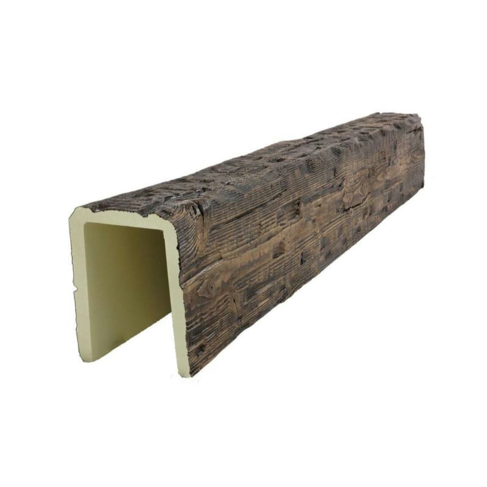
Ceiling beam installations typically require blocking members that extend from structure down through insulation to provide solid backing for beam attachment. These blocking members create deliberate thermal bridges that interrupt whatever continuous insulation strategy the ceiling assembly employs.
Standard beam blocking details use solid wood members—typically 2x material matching the thickness of ceiling framing—installed perpendicular to ceiling joists or parallel to joist direction depending on beam orientation. The blocking extends from structure through insulation cavity space down to the ceiling finish plane where it provides solid backing for beam mounting fasteners. This blocking serves essential structural functions: it distributes beam loads to structure, provides fastener holding that ceiling finish materials alone couldn't provide, and prevents deflection or damage to ceiling finishes from beam weight.
The thermal impact of this standard blocking derives from its continuous conductivity through the insulation layer. Heat flows readily through the wood blocking, effectively short-circuiting the insulation around it. The magnitude of additional heat loss depends on blocking size and number. A typical installation might use 1.5-inch-thick by 5.5-inch-wide blocking (nominal 2x6) at each beam end and at intermediate points if beam spans require it. For a 16-foot beam, this might total four blocking locations, each creating a thermal bridge of roughly 8 square inches—total 32 square inches per beam.
Calculating the thermal impact requires comparing heat flow through blocking against heat flow through equivalent area of insulated assembly. Heat flow through materials follows the relationship Q = (k × A × ΔT) / L, where Q is heat flow, k is thermal conductivity, A is area, ΔT is temperature difference, and L is thickness. For typical ceiling conditions with 12-inch insulation cavity, R-38 nominal performance, wood blocking, and 40°F temperature difference (70°F interior, 30°F attic), the additional heat loss through one square foot of blocking versus one square foot of insulation exceeds 8 Btu/hr. A building with forty beams using standard blocking might experience 100 to 150 square inches of thermal bridging, adding 80 to 120 Btu/hr heat loss—equivalent to roughly 4 to 6 square feet of completely uninsulated ceiling.
This analysis considers only steady-state conductive heat loss through blocking. Additional thermal penalty comes from convective effects where air can circulate around poorly sealed blocking, and from thermal mass effects where conductive blocking stores and releases heat cyclically. The total thermal impact can exceed simple conductive calculations by 20% to 40%.
Energy Code Implications
Building energy codes increasingly address thermal bridging through prescriptive and performance-based requirements. Understanding these code provisions helps determine when thermal bridge mitigation becomes mandatory versus merely beneficial.
Prescriptive continuous insulation requirements in IECC and ASHRAE 90.1 specify minimum R-values for continuous insulation layers in climate zones 3 through 8. These requirements recognize that insulation between framing alone provides insufficient thermal performance in colder climates. Ceiling assemblies in Climate Zones 6 through 8 require R-20 to R-25 continuous insulation or equivalent assembly performance accounting for thermal bridging. Meeting these requirements with beam blocking interrupting insulation requires either very high cavity insulation values that compensate for blocking heat loss, or blocking details that minimize thermal bridging.
Thermal envelope air barrier requirements mandate that insulation layers remain backed by continuous air barriers that prevent convective heat loss. Standard beam blocking details that penetrate insulation without careful air sealing create gaps where air can circulate around blocking, carrying additional heat through convection. Energy codes require that any penetrations through insulation be sealed to prevent this bypass airflow. Beam blocking installations must include air sealing at all interfaces between blocking and surrounding materials.
Performance path compliance using thermal modeling allows demonstrating code compliance through whole-building energy simulation rather than meeting prescriptive requirements. Projects pursuing performance path compliance must model thermal bridging effects accurately to demonstrate that actual building performance meets code. Energy modeling software includes capabilities for representing thermal bridges, allowing simulations that account for beam blocking heat loss. Buildings with extensive ceiling beam installations may find that thermal bridging effects push performance path compliance out of reach unless blocking details mitigate thermal bridging.
Continuous insulation attachment provisions in recent energy code editions specifically address fastener and blocking thermal bridging. These provisions recognize that attaching exterior continuous insulation requires fasteners penetrating the insulation, and attempt to limit thermal bridging these fasteners create. Similar concepts apply to ceiling beam blocking: the code framework increasingly expects that attachment details will minimize rather than accept thermal bridging.
Thermal Bridge Mitigation Strategies
Several detailing strategies can mitigate thermal bridging that ceiling beam blocking creates while maintaining required structural support for beam installations.
Insulated blocking assemblies replace solid wood blocking with assemblies that include insulation within the blocking configuration. One approach builds blocking from two separate wood members with rigid insulation between them: an upper member attaches to structure, a lower member provides beam fastening surface, and rigid foam board between the members creates a thermal break. The wood members remain sized to provide required structural strength while the insulation layer interrupts direct conductive path through the assembly. This approach can reduce thermal bridging by 60% to 75% compared to solid blocking.
Thermally broken standoff brackets provide mechanical attachment with minimal conductive cross-section. These proprietary products use engineering plastics or composite materials with low thermal conductivity to create standoffs between structure and beam mounting points. The insulating material carries structural loads while substantially reducing conductive heat transfer compared to wood or metal. Some products achieve thermal resistance equivalent to surrounding insulation while maintaining structural capacity for typical beam loads. Installation cost exceeds standard blocking but energy savings often justify the premium for high-performance buildings.
Reduced blocking cross-section minimizes thermal bridge area while maintaining adequate structural support. Using minimum blocking dimensions that still satisfy structural requirements reduces the conductive path area proportionally. For example, reducing blocking from nominal 2x6 to 2x4 reduces thermal bridge area by one-third while still providing adequate fastener holding for most beam applications. This approach requires verification that reduced blocking provides sufficient structural capacity but represents a simple mitigation strategy requiring no special materials.
Strategic blocking placement concentrates thermal bridges at fewer locations rather than distributing them along beam length. Standard practice might place blocking at 4-foot intervals along a long beam. Alternative details might use fewer, stronger blocking points—perhaps only at beam ends—with beam design sized to span between supports without intermediate blocking. Concentrated blocking creates the same total thermal bridge area but affects a smaller percentage of ceiling area, potentially reducing overall thermal impact through edge effects where heat spreads through surrounding materials.
Installation Detailing for Thermal Performance
Proper installation details and techniques ensure that thermal bridge mitigation strategies achieve their intended performance. Several aspects of detailing deserve attention.
Air sealing at all blocking interfaces prevents convective heat loss that compounds conductive thermal bridging. Sealant or spray foam should fill gaps between blocking and surrounding ceiling materials, between blocking components if insulated assemblies are used, and around any fasteners or brackets. This air sealing ensures that heat transfer occurs only through conduction—which mitigation strategies address—rather than through uncontrolled air leakage that no mitigation approach can prevent.
Insulation installation quality around blocking affects thermal performance substantially. Insulation should be carefully fitted to blocking with no gaps or voids that create additional thermal bypass. Where blocking interrupts batt insulation, batts should be cut carefully to fit snugly against all blocking faces. Where spray foam or blown insulation is used, installation should ensure complete fill around blocking without voids. Thermal imaging during installation can verify quality and identify problem areas requiring correction.
Thermal bridge connector detailing where insulated blocking assemblies or standoff brackets connect to structure should minimize conducting elements. Screws or bolts connecting brackets to structure create point thermal bridges at each fastener location. Using minimum number and size of fasteners that satisfy structural requirements reduces this effect. Some thermally-broken bracket systems include washers or standoffs that minimize fastener thermal contact area, further reducing bridging.
Vapor control coordination ensures that thermal bridge mitigation details don't compromise moisture management. Building assemblies in heating climates typically include vapor retarders on the warm side of insulation to prevent moisture diffusion into cold cavity spaces where condensation could occur. Blocking details must maintain vapor control continuity. If rigid insulation used in insulated blocking assemblies has low vapor permeability, it may function as a vapor retarder itself. If not, separate vapor retarder should be detailed at blocking locations to maintain continuity.
Cost-Benefit Analysis
Thermal bridge mitigation at beam blocking involves additional cost compared to standard blocking details. Evaluating whether this cost is justified requires comparing incremental expenses against energy savings and other benefits.
Material cost for thermal bridge mitigation varies by strategy. Insulated blocking assemblies using standard lumber plus rigid foam board might add $15 to $30 per blocking point compared to solid blocking. Proprietary thermally-broken brackets can range from $25 to $80 per location depending on load requirements and product selection. For a building with forty beams requiring four blocking points each (160 total locations), material cost premiums might range from $2,400 to $12,800 depending on the approach selected.
Labor cost typically increases modestly because thermal bridge mitigation details require more complex assembly than solid blocking. Fabricating insulated blocking assemblies or installing specialized brackets takes more time than cutting and installing solid blocking. Labor premiums might add 50% to 100% to blocking installation time—perhaps 5 to 10 additional minutes per location. For the example building, this might total 13 to 26 additional labor hours, costing $500 to $1,300 at typical trade labor rates.
Energy savings from thermal bridge mitigation depend on climate, energy costs, and building systems efficiency. The example building discussed earlier—where thermal bridging degraded performance by 8%—might have annual heating and cooling costs around $12,000. An 8% reduction represents $960 annual savings. With material and labor premiums totaling perhaps $4,000 for the mitigation strategy selected, simple payback occurs in roughly 4 years. Over the building's thirty-year design life, cumulative savings exceed $28,000 assuming stable energy costs, providing excellent return on investment.
Carbon emissions reduction provides environmental benefits beyond direct economic savings. Buildings account for roughly 40% of energy consumption and carbon emissions in developed countries. Reducing building energy consumption addresses climate change impacts while also hedging against future carbon pricing schemes. For the example building, an 8% performance improvement might prevent 2 to 3 metric tons of annual CO₂ emissions, totaling 60 to 90 tons over building life—equivalent to taking 15 to 20 cars off the road for a year.
Integration with Other Building Systems
Thermal bridge mitigation details for ceiling beam blocking must coordinate with other building systems that also interact with ceiling assemblies. Integrated design considers these interactions from project inception rather than attempting to reconcile conflicts later.
Structural framing coordination ensures that blocking attachment points align with framing members capable of supporting beam loads. Thermally-broken standoff brackets typically require attachment to solid framing rather than ceiling finish materials. Structural drawings should identify acceptable attachment locations, and architectural beam layout should position beams where blocking can connect appropriately. This coordination prevents field situations where desired beam locations don't align with structure capable of supporting them.
Electrical and mechanical systems often occupy ceiling cavity spaces where beam blocking installs. Recessed lighting, HVAC equipment, and electrical junction boxes compete for space with beam blocking. Integrated ceiling plans showing all systems help identify conflicts before installation. Some situations may require relocating mechanical or electrical components; others may require adjusting beam locations to avoid existing equipment. Early coordination resolves these potential conflicts during design rather than in field.
Acoustic performance of ceiling assemblies can be affected by beam blocking that bridges sound-isolating construction. Buildings requiring high acoustic separation between floors use discontinuous ceiling/floor assemblies where ceiling structure mounts separately from floor structure above. Beam blocking that connects through both structures creates flanking paths for sound transmission, degrading acoustic isolation. Acoustically-sensitive projects require evaluating whether beam blocking creates unacceptable flanking and potentially designing blocking details that maintain acoustic separation.
Fire-rated ceiling assemblies subject to fire resistance testing often include limitations on penetrations and modifications that could affect rating. Adding beam blocking to rated ceiling assemblies requires verifying that the blocking doesn't compromise fire resistance. Most rated assemblies allow limited penetrations for mechanical and electrical services under specific conditions. Beam blocking should be designed to meet these conditions, or the overall assembly may require retesting or engineering evaluation to verify that fire rating is maintained.
Quality Control and Verification
Ensuring that installed thermal bridge mitigation details perform as designed requires quality control during construction and verification after completion.
Shop drawing review should specifically address thermal bridge mitigation details. Contractor-prepared shop drawings often provide the first opportunity to identify whether installation approach matches design intent. Reviewers should verify that shop drawings show proper blocking configuration, appropriate materials, required air sealing, and correct integration with surrounding insulation. Discrepancies should be resolved before fabrication and installation begin.
Site observation during installation verifies that work proceeds according to approved details. For critical projects, construction administration should include site visits during beam blocking installation to observe techniques and materials. Observations might include verifying blocking dimensions, confirming that insulation is installed properly around blocking, and checking that air sealing is completed. Site observation provides opportunities to correct problems immediately rather than discovering them through later investigation.
Thermal imaging after installation completion can verify thermal performance and identify any unanticipated thermal bridging. Infrared cameras visualize surface temperature patterns that reveal heat loss through thermal bridges. Imaging conducted during cold weather with significant indoor-outdoor temperature difference clearly shows whether beam blocking creates visible thermal bridges or whether mitigation details successfully interrupt heat flow. Any identified problems can be addressed through retrofit air sealing or supplemental insulation.
Blower door testing measures air leakage that might indicate inadequate air sealing at blocking penetrations. Whole-building blower door tests determine total building leakage and are often required for energy code compliance or green building certification. Excessive leakage might prompt investigation to identify sources, potentially including beam blocking penetrations. Supplemental infrared imaging conducted during blower door testing can specifically locate air leakage points requiring remediation.
The office building project mentioned in the opening implemented thermal bridge mitigation using insulated blocking assemblies fabricated from 2x4 lumber with 2-inch polyisocyanurate rigid foam board sandwiched between members. The assemblies achieved approximately R-10 thermal resistance—not equivalent to the surrounding R-38 but far superior to solid blocking. Combined with careful air sealing, the details reduced thermal bridging by an estimated 75% compared to solid blocking, limiting building performance degradation to under 2% rather than the 8% that standard details would have caused. Post-occupancy thermal imaging confirmed minimal heat loss at beam blocking locations, validating the mitigation strategy's effectiveness.
Continuous insulation thermal bridge mitigation at ceiling beam blocking exemplifies how building science principles increasingly inform architectural detail design. Details that once concerned only structural adequacy and visual appearance now must also address thermal performance, air leakage control, and overall building energy efficiency. As energy codes continue evolving toward higher performance requirements, thermal bridge mitigation progresses from optional enhancement to standard practice. Projects that integrate these considerations from initial design create buildings where decorative architectural elements support rather than compromise overall building performance.
Technical References
ASTM standards cited in every specification
Test Data
Lab results from internal testing program
Updated 2026
Reviewed against current product specs