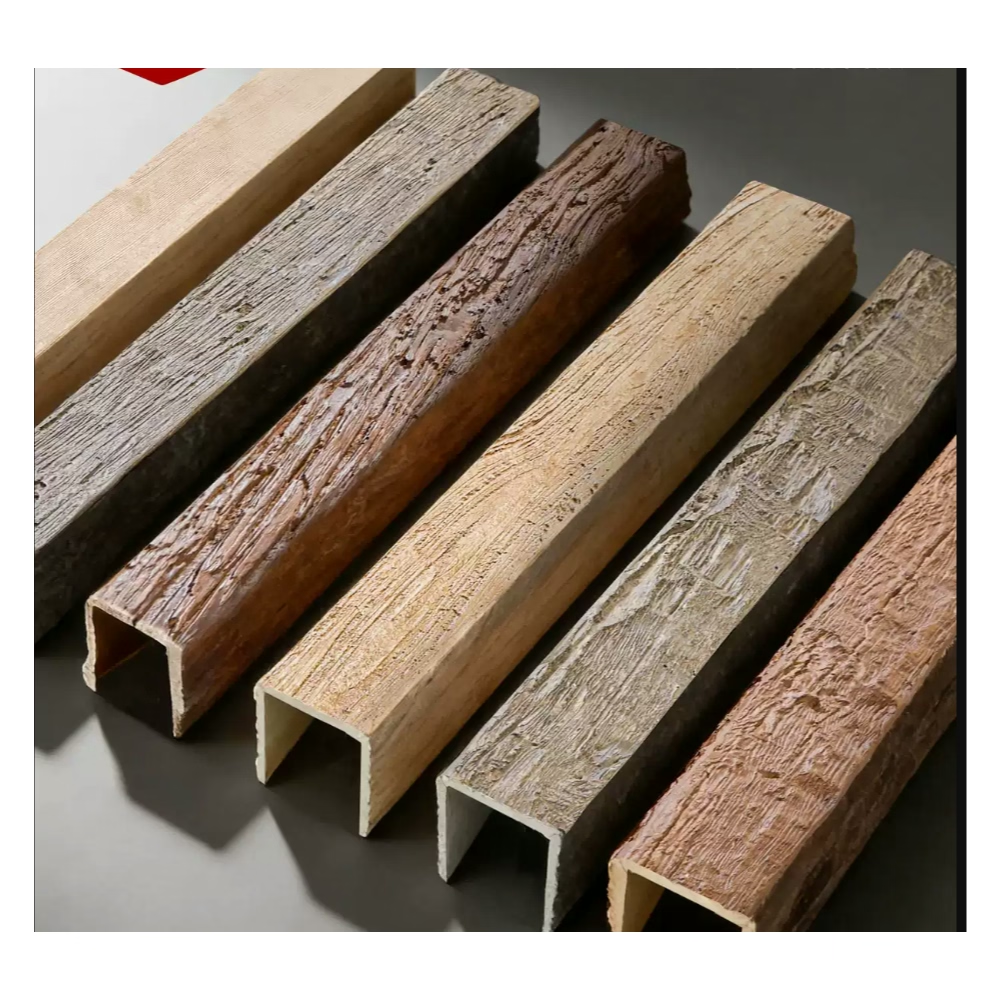
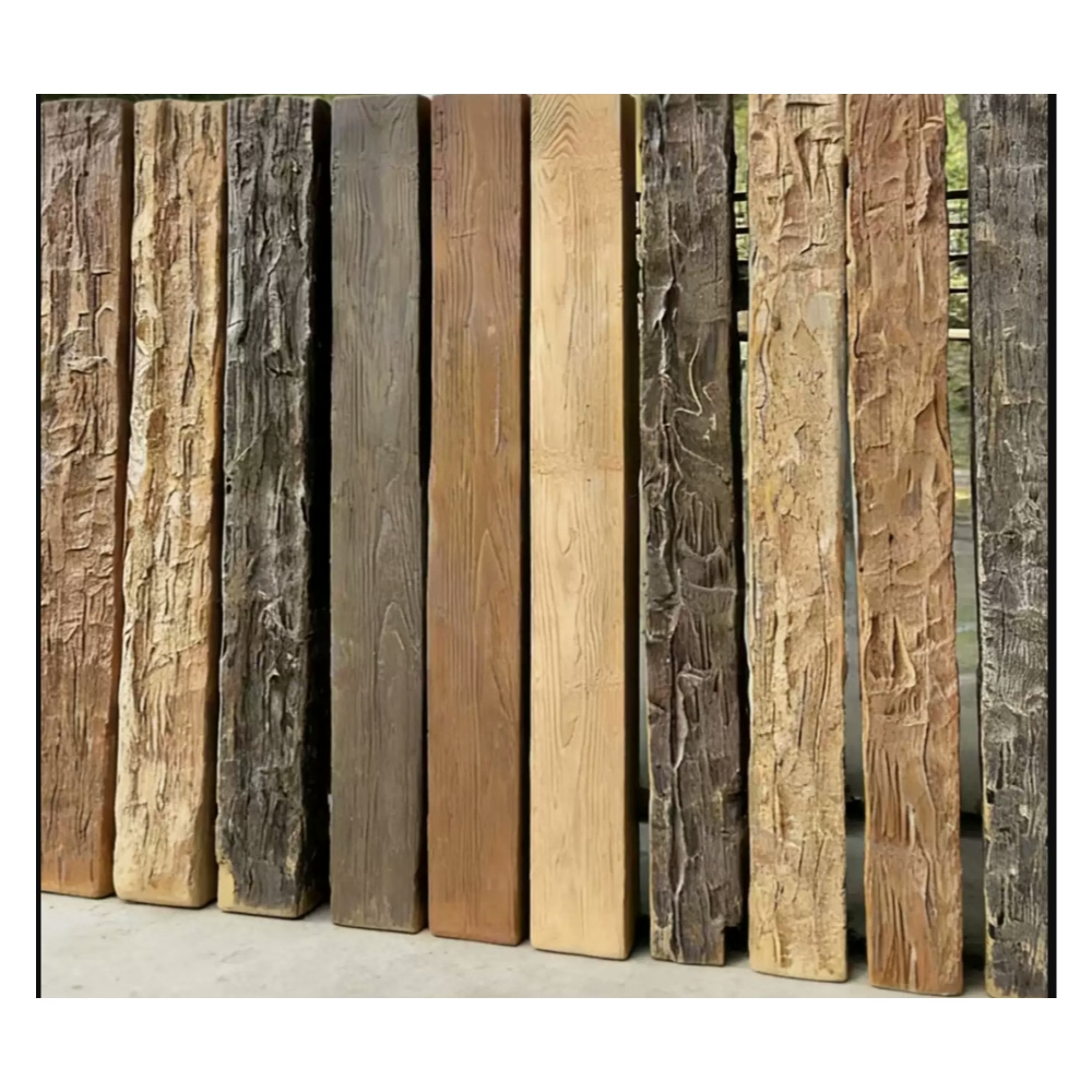
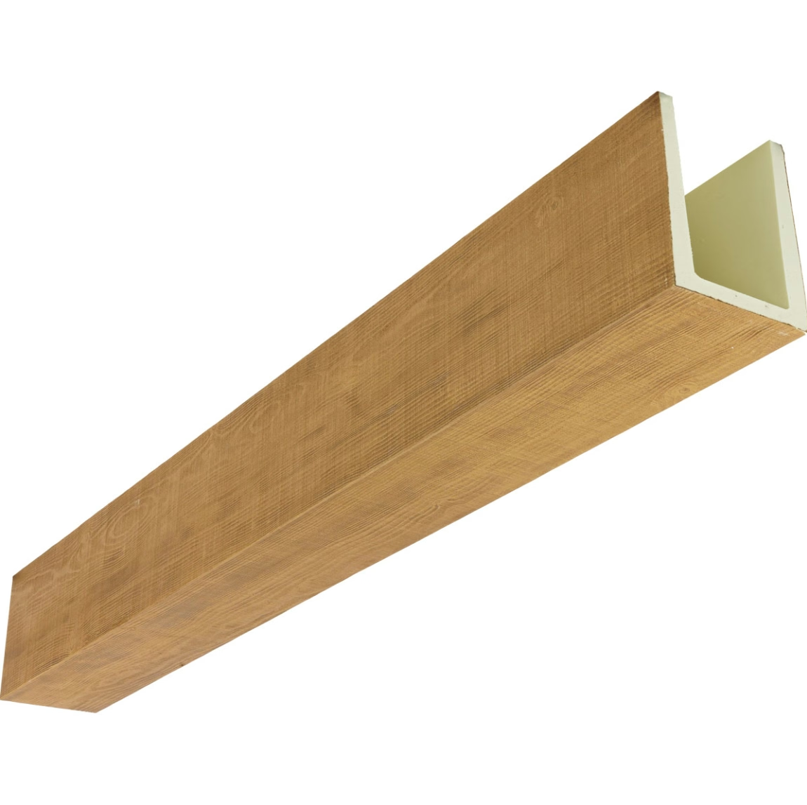
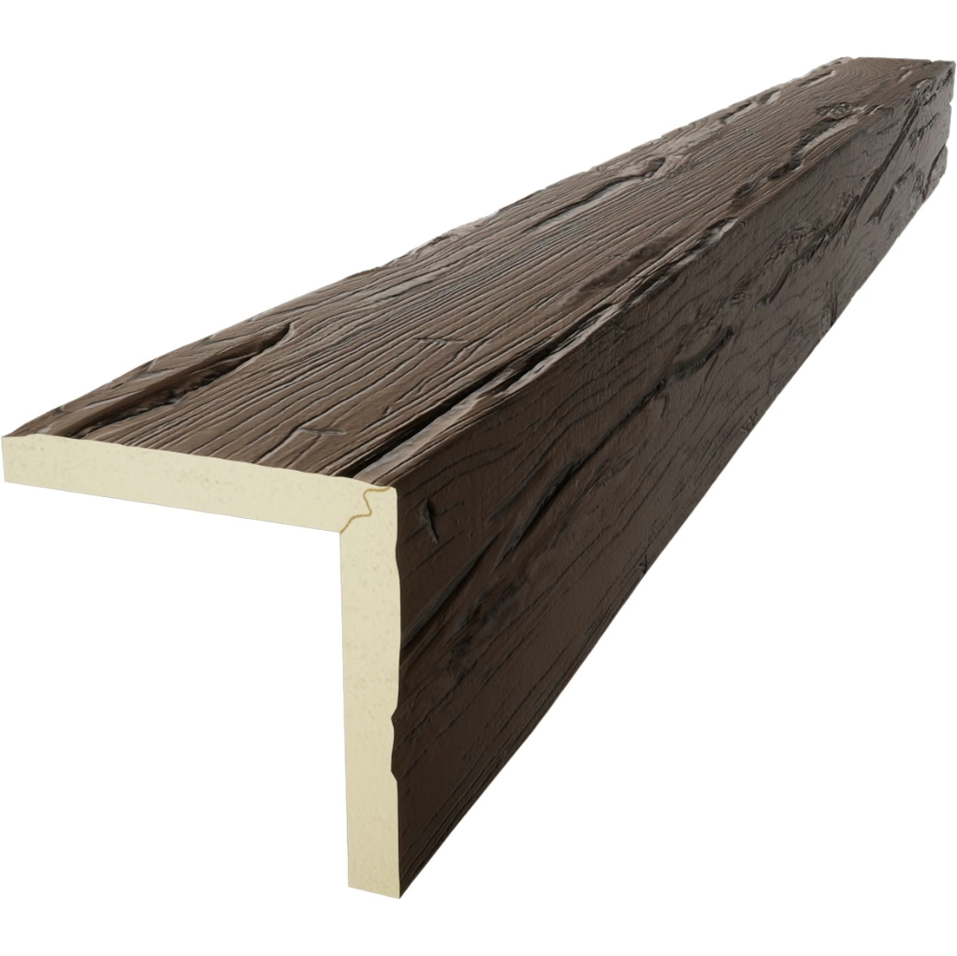
The project architect reviewing construction progress photos from a high-end residential project in Phoenix noticed worrying details in ceiling beam installations: visible gaps had opened between decorative faux wood beams and adjacent drywall ceiling surfaces in the great room despite installation having been completed just six weeks earlier. Site investigation during a hot afternoon revealed gaps measuring 3/16 to 1/4 inch at multiple beam-to-ceiling transitions that the installing contractor insisted had been tight during installation in mild spring weather. Temperature measurements confirmed the problem source: ceiling surface temperatures reached 96°F in afternoon sun exposure, compared to the 68°F interior temperature maintained during installation. The 28°F temperature increase caused the polyurethane beams—with coefficient of thermal expansion nearly four times that of gypsum board—to expand substantially more than surrounding ceiling materials. The differential expansion created gaps at restrained locations and buckled beams at others where expansion had nowhere to go. Remediation required removing beams, installing flexible expansion joints at strategic locations, and detailing mounting systems to allow free thermal movement. The additional work cost $11,000 and delayed project completion by three weeks.
Coefficient of thermal expansion matching for multi-material ceiling assemblies addresses a material compatibility challenge that arises whenever building assemblies combine materials with different thermal expansion characteristics. All materials expand when heated and contract when cooled, but expansion magnitude varies dramatically by material type. Metals expand substantially; concrete and masonry expand moderately; wood expands minimally (in grain direction). Plastics including polyurethane typically expand considerably—often exceeding metals. When materials with mismatched thermal expansion coefficients connect rigidly in assemblies experiencing temperature changes, differential movement creates internal stress that can cause cracking, distortion, connection failure, or visible gap formation. Understanding material thermal properties, predicting movement magnitudes, and detailing appropriate accommodation prevents these problems in decorative ceiling installations combining polyurethane beams with structural materials having different expansion characteristics.
Thermal Expansion Fundamentals
Material thermal expansion follows predictable physical principles that allow quantitative analysis of movement magnitudes and stress development.
Coefficient of thermal expansion (CTE) quantifies dimensional change per degree of temperature change, typically expressed in units of strain per degree (in/in/°F or mm/mm/°C). Materials with high CTE values expand and contract substantially with temperature changes; those with low CTE remain dimensionally stable. Representative CTE values for common building materials span two orders of magnitude: steel 6.5 × 10⁻⁶ in/in/°F, aluminum 13 × 10⁻⁶, concrete 5.5 × 10⁻⁶, gypsum board 9 × 10⁻⁶, wood (parallel to grain) 2 × 10⁻⁶, wood (perpendicular to grain) 30 × 10⁻⁶, and polyurethane foam 30 to 80 × 10⁻⁶ depending on formulation and density.
Linear expansion calculation for unrestrained materials uses the relationship ΔL = α × L × ΔT, where ΔL is length change, α is coefficient of thermal expansion, L is original length, and ΔT is temperature change. A 16-foot (192-inch) polyurethane beam with CTE of 50 × 10⁻⁶ in/in/°F experiencing 30°F temperature increase expands ΔL = 50 × 10⁻⁶ × 192 × 30 = 0.288 inches (approximately 9/32 inch). This nearly 5/16-inch movement must be accommodated somewhere in the assembly—either through flexible connections, deliberate gaps that close during expansion, or material stress if movement is completely restrained.
Restraint conditions dramatically affect whether thermal movement creates problems. Completely unrestrained materials expand and contract freely without developing internal stress—the dimensional changes are accommodated through movement. Completely restrained materials cannot move, so temperature changes create thermal stress proportional to attempted movement and material stiffness. Most real situations fall between these extremes, with partial restraint allowing some movement while developing some stress. Connection details and assembly configuration determine restraint level and thus whether thermal effects cause problems.
Stress development in restrained materials follows σ = E × α × ΔT, where σ is thermal stress, E is elastic modulus, α is thermal expansion coefficient, and ΔT is temperature change. For polyurethane foam with typical E = 10,000 psi, α = 50 × 10⁻⁶ in/in/°F, experiencing 30°F temperature increase while completely restrained, thermal stress reaches 10,000 × 50 × 10⁻⁶ × 30 = 15 psi. While this stress level appears modest, it can exceed adhesive bond strength or cause cumulative damage through repeated thermal cycling.
Temperature Environments in Building Ceilings
Ceiling assemblies experience diverse temperature environments depending on building type, climate, and specific location within buildings. Understanding these environments helps predict thermal movement magnitudes.
Attic-backed ceiling assemblies in buildings with unconditioned attic spaces above experience the most extreme temperature variations. Summer attic temperatures in hot climates routinely reach 130-150°F while conditioned spaces below maintain 70-75°F. Winter conditions reverse the gradient with moderate interior temperatures above cold attic spaces. Ceiling surfaces in these conditions experience temperature variations approaching 60-80°F seasonally, creating substantial thermal expansion demands. The temperature gradient through ceiling thickness creates additional complexity because upper and lower beam surfaces may experience different temperatures, potentially causing thermal bowing.
Conditioned ceiling cavities in buildings with HVAC equipment, ductwork, or other heat sources in ceiling plenum spaces experience moderate temperature variations. Plenum temperatures typically range 10-20°F above or below conditioned space temperatures depending on equipment operation and insulation effectiveness. These moderate temperature swings create less dramatic thermal movements than attic conditions but still require consideration, particularly for long beam spans where even modest CTE mismatches accumulate to visible movements.
Exposed ceiling structure in buildings without suspended ceilings or where beams attach to exposed concrete or steel experiences temperatures determined by HVAC system performance and thermal mass effects. Well-controlled interior environments limit temperature swings to perhaps 10-15°F seasonally, creating relatively benign conditions for thermal expansion. However, spaces with variable occupancy, thermostat setback strategies, or buildings that experience shutdown periods (warehouses, schools during summer break) may experience larger temperature variations requiring accommodation.
Solar heat gain through skylights or glazed areas creates localized temperature peaks exceeding general ambient conditions. Ceiling beams positioned near skylights or south-facing glass walls in sunny climates may experience direct or indirect solar heating raising local temperatures 20-30°F above general ceiling temperatures. These localized thermal effects require evaluation separate from general ceiling conditions.
Material-Specific Thermal Properties
Different beam materials and ceiling substrates have distinct thermal expansion characteristics affecting assembly compatibility.
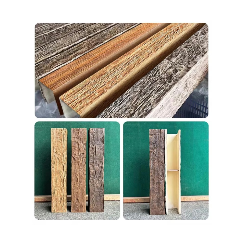
Polyurethane foam beams exhibit high thermal expansion coefficients generally ranging from 30 to 80 × 10⁻⁶ in/in/°F depending on specific formulation, density, and foam structure. Closed-cell polyurethane formulations common in decorative beams typically fall in the 40 to 60 × 10⁻⁶ range—substantially higher than most structural building materials. This high CTE means polyurethane beams expand considerably with temperature increases, requiring accommodation in installation details. Additionally, polyurethane's relatively low elastic modulus means thermal expansion creates less stress in restrained conditions compared to stiffer materials attempting equal movement.
Gypsum board ceiling substrates have moderate thermal expansion around 9 × 10⁻⁶ in/in/°F—substantially lower than polyurethane. This mismatch means beam-to-ceiling assemblies experience differential movement of roughly 40 × 10⁻⁶ (the difference between polyurethane at 50 × 10⁻⁶ and gypsum at 10 × 10⁻⁶) for each degree of temperature change. Over realistic temperature ranges and beam lengths, this differential accumulates to visible movements requiring accommodation.
Wood ceiling substrates including tongue-and-groove planking or exposed wood sheathing have complex thermal expansion characteristics depending on grain orientation. Parallel to grain, wood exhibits very low CTE around 2 to 3 × 10⁻⁶—even lower than gypsum board. Perpendicular to grain, wood CTE increases dramatically to 30-50 × 10⁻⁶, approaching polyurethane values. Wood ceiling installations with grain running parallel to beam orientation create maximum CTE mismatch; perpendicular grain orientations create better matching. However, wood moisture content changes typically dominate dimensional changes over thermal effects.
Concrete and steel ceiling substrates in commercial construction have relatively low thermal expansion coefficients (5-7 × 10⁻⁶ for both materials by fortunate coincidence). Beams mounting to these substrates experience substantial CTE mismatch with polyurethane. However, the high stiffness of concrete and steel means substrate materials provide effectively rigid reference that doesn't accommodate beam movements—thermal expansion must be accommodated entirely through beam mounting details or beam material strain.
Predicting Thermal Movement Magnitude
Quantitative prediction of thermal movements allows designers to detail appropriate accommodation before installation.
Design temperature range determination establishes the total temperature variation that assemblies will experience. Conservative practice uses maximum and minimum ceiling temperatures expected during normal building operation—not just average conditions. For attic-backed ceilings in hot climates, design ranges might span 60-80°F between winter and summer extremes. Conditioned interior ceilings might use 15-20°F ranges. Site-specific temperature monitoring in existing similar buildings provides the most accurate data; lacking monitoring, conservative assumptions based on climate and building type provide reasonable estimates.
Differential movement calculation compares thermal expansion between different materials in assemblies. For a 16-foot polyurethane beam (CTE = 50 × 10⁻⁶) mounted to gypsum ceiling (CTE = 10 × 10⁻⁶) experiencing 40°F temperature increase: beam expansion = 50 × 10⁻⁶ × 192 × 40 = 0.384 inches; ceiling expansion = 10 × 10⁻⁶ × 192 × 40 = 0.077 inches; differential movement = 0.384 - 0.077 = 0.307 inches (approximately 5/16 inch). This 5/16-inch differential must be accommodated to prevent gaps or stress.
Cumulative effects over multiple thermal cycles can cause progressive damage even when single-cycle movements appear accommodated. Adhesive bonds might withstand initial expansion but weaken progressively with repeated stress cycling. Flexible sealants might accommodate initial movement but lose elasticity after repeated stretching. Design should consider not just single-event movement but durability through thousands of thermal cycles over building life.
Seasonal versus diurnal temperature variations have different design implications. Large seasonal temperature swings create maximum single-event movements requiring accommodation range in movement-permitting details. Rapid diurnal cycles (day-night temperature variations) create fatigue loading that can progressively damage materials even if movement magnitudes per cycle are modest. Both effects require consideration in critical applications.
Accommodation Strategies
Several detailing approaches accommodate differential thermal movement while maintaining assembly function and appearance.
Expansion joints at strategic locations allow free thermal movement without restraint. For long beam installations, dividing continuous runs into shorter segments separated by planned expansion joints prevents movement accumulation. Joints might locate at beam splices using decorative strap covers that conceal gaps while allowing movement, or at beam-to-wall transitions where small gaps can be detailed as intentional reveals. Joint spacing depends on anticipated movement magnitude—generally targeting maximum movement at any joint under 1/4 inch to maintain visual acceptance while providing adequate accommodation.
Flexible mounting that allows beam sliding relative to ceiling substrate permits thermal expansion without loading connections. One common detail fixes beam mounting rigidly at one location (typically beam center) while both ends attach through slotted connections permitting sliding. As temperature increases, the beam expands equally in both directions from the fixed center point, with ends sliding outward through slotted connections. The reverse occurs during cooling. This approach maintains beam position visually while accommodating dimensional changes.
Flexible sealant joints at beam-to-ceiling interfaces accommodate movement through elastomeric material stretching and compressing. Instead of rigid adhesive bonds or hard caulking, flexible sealants (silicone, polyurethane, or hybrid polymer formulations) bond to both surfaces while accommodating movement through elastic deformation. Sealant selection should specify movement capability matching predicted differential expansion—typically ±25% to ±50% of joint width. Joint design should size initial gap width to center anticipated movement range, allowing equal capacity for expansion and contraction.
Material selection matching thermal expansion characteristics where possible reduces differential movement magnitude. While polyurethane beams inherently have high CTE relative to most structural materials, manufacturers offer different formulations with varying thermal expansion. Specifying lower-expansion polyurethane formulations where available reduces accommodation demands. Similarly, selecting ceiling finish materials with relatively high CTE (avoiding low-expansion options like fiber-cement board) reduces mismatch with polyurethane beams.
Multi-Material Assembly Design
Ceiling assemblies often combine multiple materials beyond just beams and primary ceiling surfaces, complicating thermal expansion coordination.
Beam-to-wall transitions introduce additional material interfaces where thermal movement must be accommodated. Interior partition walls might be gypsum board on metal studs (high CTE), wood stud framing (low CTE in vertical direction), masonry (moderate CTE), or concrete (low CTE). Each combination creates different thermal compatibility with beams. Detailing beam terminations at walls should consider not just beam thermal expansion but also how wall materials move relative to ceiling planes.
Ceiling-mounted mechanical systems including light fixtures, HVAC registers, and sprinkler heads create rigid reference points that may not accommodate beam thermal movement. Beams passing over or around these fixed elements require accommodation details preventing interference as beams expand. Where beams contact or closely approach fixed elements, expansion gaps or flexible connection details prevent thermal binding.
Multi-directional beam patterns with intersecting beams in grid or coffered configurations create complexity because thermal expansion occurs simultaneously in perpendicular directions. Intersections require accommodation allowing movement in both beam directions without restraint. Floating intersection details where crossing beams don't bond to each other provide this accommodation, though careful detailing maintains visual appearance of solid intersections.
Truss or structural beam integration where decorative beams wrap or attach to structural members introduces high-stiffness elements that provide minimal accommodation. Structural steel or engineered wood trusses essentially provide rigid references against which decorative beams must accommodate their thermal expansion. Mounting details should isolate decorative beams from structural members through flexible connections or should detail decorative beams as panels that can slide relative to structure.
Installation Considerations
Proper installation practices ensure that designed accommodation strategies function as intended throughout building service life.
Installation temperature affects initial joint gap sizing and mounting system positioning. Assemblies installed during cool weather should position expansion joints near their closed positions, allowing thermal expansion into available gap width as temperatures rise. Installation during hot weather requires the opposite—joints near their open positions with room for gap closing as temperatures eventually fall. Installation temperature recording helps future maintenance personnel understand whether observed conditions represent expansion, contraction, or some intermediate state.
Fastener torque and adhesive application methods affect how effectively flexible mounting systems accommodate movement. Over-tightened fasteners in slotted connections can create friction preventing sliding despite slots providing dimensional capacity. Excessive adhesive squeeze-out can bond surfaces that details intended to remain free-sliding. Installation specifications should address these details explicitly, and site observation should verify proper execution.
Thermal conditioning during installation by installing beams after buildings reach normal operating temperatures and temperature ranges reduces movement that must be accommodated after completion. Buildings that install decorative finishes including beams before HVAC systems operate may expose installations to unusually hot or cold conditions during construction, causing initial movements exceeding design assumptions. Where practical, deferring finish installations until buildings achieve stable environmental conditions improves outcomes.
Pre-installation planning identifying high-stress details likely to require particular care focuses quality control efforts effectively. Longest beam spans, locations with maximum temperature exposure, transitions where beams meet dissimilar materials—these details warrant extra attention during installation to ensure accommodation provisions function properly. Planning sessions with installing trades help ensure understanding of critical details and installation sequence requirements.
Quality Control and Performance Verification
Post-installation verification and ongoing monitoring confirm that thermal accommodation strategies perform as designed.
Dimensional verification immediately after installation establishes baseline conditions documenting initial gap widths at expansion joints, positions within slotted connections, and sealant joint configurations. These baseline records allow comparing future observations to determine whether observed conditions represent normal thermal movement or indicate problems requiring investigation.
Seasonal observation during both temperature extremes verifies that accommodation provisions function through full design range. Initial observations shortly after installation show conditions at installation temperature but don't confirm behavior at temperature extremes. Follow-up observations during seasonal temperature peaks and minimums verify that joints move as anticipated without exceeding available capacity or developing visible distress.
Thermal cycling testing for critical applications can artificially create temperature variations to verify accommodation provisions without waiting for seasonal changes. Portable heaters gradually warming ceiling spaces while monitoring beam response, or allowing buildings to cool below normal operating temperatures during unoccupied periods, creates temperature variations revealing how installations respond. This accelerated testing provides confidence before buildings enter normal service.
Problem identification criteria establish objective standards for determining when observed conditions warrant investigation or remediation. Some gap opening or closing represents normal thermal accommodation and doesn't indicate problems. Criteria might specify that gaps exceeding 3/8 inch, visible beam buckling, cracking in beam material, or adhesive failure warrant investigation—while smaller movements are accepted as normal performance.
Case Study: Arizona Residence Remediation
The Phoenix residence project described in the opening provides instructive example of thermal expansion problem diagnosis and remediation.
Detailed thermal analysis after problem identification measured actual ceiling temperatures throughout daily cycles and seasonally. Data logging over several weeks revealed ceiling temperatures ranging from 62°F during winter evenings to 98°F during summer afternoons—36°F range. Beam temperatures measured slightly higher than ceiling averages due to darker beam colors absorbing radiant heat. Original installation had occurred during April with mild temperatures around 72°F—near the middle of the annual range, making both expansion and contraction from installation conditions substantial.
Material testing determined actual polyurethane CTE for installed beams at 56 × 10⁻⁶ in/in/°F—higher than generic values. The 16-foot beam spans combined with 36°F temperature range and 56 × 10⁻⁶ CTE produced theoretical expansion of 56 × 10⁻⁶ × 192 × 36 = 0.387 inches (approximately 3/8 inch). Gypsum ceiling expansion over the same conditions totaled only 0.069 inches (approximately 1/16 inch), creating differential movement of 5/16 inch—closely matching observed gap dimensions.
Remediation design incorporated expansion joints at beam-to-wall transitions using flexible urethane sealant in 1/4-inch-wide joints. Beam mounting changed from continuous adhesive to hybrid system using rigid attachment at beam centers with flexible adhesive (allowing some movement) for outer thirds of beam lengths. Sealant joint sizing provided 1/8 inch initial gap during installation (estimated mid-range temperature), allowing 1/8 inch expansion capacity (gap closing to zero at hot extremes) and equal contraction capacity (gap opening to 1/4 inch at cold extremes).
Post-remediation monitoring over one year confirmed successful performance. Sealant joints were observed to vary from near-zero width during hot weather to approximately 3/16 inch during cool periods—within design capacity and visually acceptable. No gaps developed at beam-to-ceiling interfaces, indicating that hybrid mounting system successfully accommodated movements. Homeowner satisfaction with remediated installation validated that problem resolution maintained aesthetic intent while eliminating thermal expansion issues.
Coefficient of thermal expansion matching for multi-material ceiling assemblies exemplifies how material science fundamentals directly affect architectural detail performance. Building assemblies routinely combine materials with vastly different thermal properties, creating differential movement that must be accommodated through appropriate detailing. Projects that understand material thermal characteristics, quantify expected movements, and detail accommodation provisions create assemblies that perform reliably through thousands of thermal cycles over building lifetimes. Those that ignore thermal expansion effects—treating assemblies as if materials were dimensionally stable—discover problems after installation when remediation costs substantially more than proper initial design would have required. The modest additional design effort to address thermal expansion prevents problems while maintaining installation integrity despite inevitable temperature variations.
Technical References
ASTM standards cited in every specification
Test Data
Lab results from internal testing program
Updated 2026
Reviewed against current product specs