The building inspector reviewing final installations in a newly completed hotel conference center identified a code violation that would delay occupancy: decorative beams installed in the ballroom ceiling violated fire sprinkler clearance requirements specified in NFPA 13. Eight beam locations placed substantial obstructions too close to sprinkler heads, creating shadow areas where spray patterns could not provide adequate coverage. The fire protection contractor had installed sprinklers according to approved shop drawings that predated the beam layout revisions the interior designer had made during construction. Neither the design team nor the general contractor had coordinated the changes with the fire protection system. Remediation required relocating four sprinkler heads and removing portions of three beams—work that consumed two weeks and cost $18,000 in labor, materials, and schedule delay.
Fire sprinkler clearance requirements around decorative ceiling beams represent one of the most technically specific—and frequently misunderstood—aspects of beam ceiling installation. Building codes mandate particular spatial relationships between sprinkler heads and ceiling obstructions to ensure that water distribution patterns provide adequate fire protection coverage. These requirements derive from extensive fire testing that has quantified how various obstruction configurations affect sprinkler performance. Understanding and applying these requirements during design prevents the costly conflicts that emerge when decorative treatments and life safety systems are coordinated inadequately.
NFPA 13 Obstruction Rules
The National Fire Protection Association's NFPA 13 standard for sprinkler system installation contains detailed requirements for sprinkler positioning relative to ceiling obstructions. These rules, developed through decades of fire testing and real-world fire performance analysis, specify minimum distances that must separate sprinkler heads from beams, joists, ducts, and other ceiling elements that could interfere with water distribution.
The fundamental principle underlying obstruction rules recognizes that ceiling elements projecting below the plane of sprinkler heads can block water spray patterns, creating unprotected areas. Water discharged from an activated sprinkler flows outward in a roughly hemispherical pattern that ceiling obstructions can intercept. Obstructions positioned too close to sprinkler heads prevent water from reaching areas beyond the obstruction, creating "shadow zones" where fire could spread unchecked.
NFPA 13 quantifies acceptable obstruction proximity through specific dimensional criteria that vary based on obstruction size and sprinkler type. For standard spray sprinklers—the most common type in most occupancies—the code distinguishes between obstructions of different depths. Beams projecting less than 4 inches below sprinkler deflectors are treated as minor obstructions with relaxed clearance requirements. Those projecting 4 inches or more are considered significant obstructions requiring greater separation from sprinkler heads.
The 4-inch threshold reflects the depth at which testing has shown that obstruction effects become substantial enough to compromise coverage. Shallow beams cause some disruption to spray patterns but not enough to create unprotected areas of concerning size. Deeper beams can block significant portions of spray patterns, potentially leaving areas unprotected unless sprinklers are positioned to avoid the blocking effect.
For beams exceeding the 4-inch depth threshold, NFPA 13 specifies that sprinkler heads must maintain particular distances from the obstruction. The minimum horizontal distance between a sprinkler deflector and the nearest edge of a beam depends on how far the beam projects below the sprinkler. Beams projecting 4 to 12 inches below sprinklers require different clearances than those projecting 12 to 24 inches, with clearance requirements increasing as beam projection depth increases.
Beam Depth and Material Considerations
The physical characteristics of decorative ceiling beams—particularly depth and cross-sectional configuration—directly affect how they interact with fire sprinkler requirements. Understanding these relationships helps designers select and position beams that minimize conflicts with fire protection systems.
Beam depth measured from the finished ceiling surface to the bottom face of the beam determines whether the beam qualifies as a significant obstruction requiring increased sprinkler clearance. Polyurethane faux beams are available in depths ranging from approximately 5 inches to 12 inches or more for standard products, with custom profiles sometimes extending deeper. Most common beam selections fall into the category of significant obstructions that trigger clearance requirements.
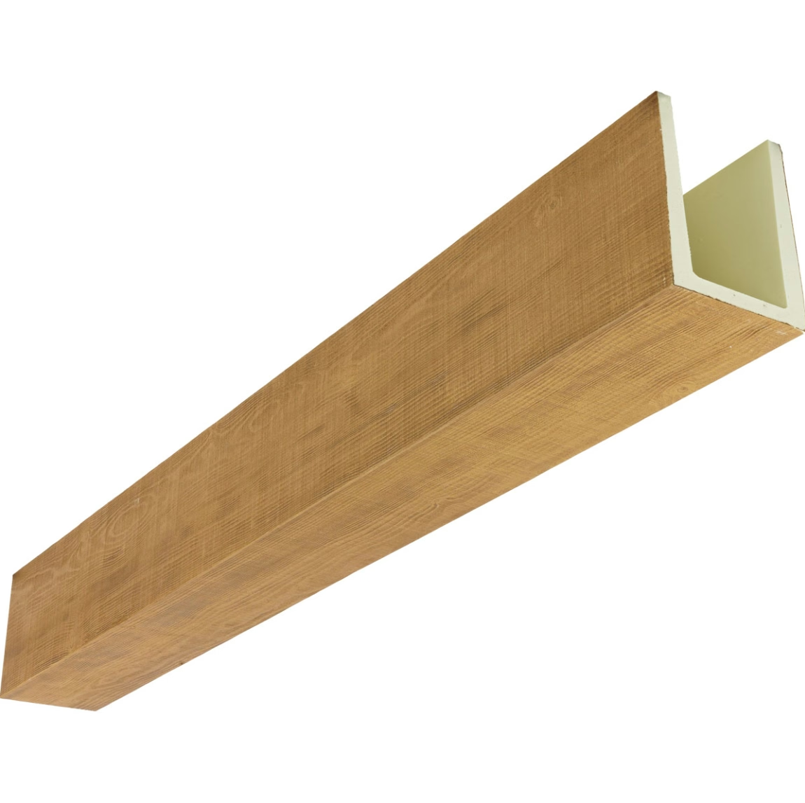
The three-sided hollow configuration typical of faux beam products creates a cross-section where the beam projects below ceiling surfaces while leaving the interior space open. This configuration affects fire sprinkler interaction differently than solid rectangular obstructions of the same external dimensions. Some jurisdictions and fire protection engineers interpret code requirements for hollow beams more flexibly than for solid obstructions, reasoning that the open interior allows some water penetration that solid beams would block completely. However, this interpretation is not universal, and conservative application of code requirements treats hollow beams as full obstructions of their external dimensions.
Beam width—the horizontal dimension parallel to the ceiling surface—affects the extent of spray pattern obstruction but does not change the basic clearance requirements. Wider beams create larger shadow zones than narrow beams of the same depth, but NFPA 13 clearance rules apply equally regardless of width. The wider shadow zones created by wider beams may require additional sprinkler heads to ensure adequate coverage of areas beyond the obstruction, but the minimum distance separating sprinklers from beam edges remains determined by depth rather than width.
Material fire performance characteristics of polyurethane beams occasionally raise questions about whether their combustibility affects clearance requirements. NFPA 13 obstruction rules are based primarily on physical interference with spray patterns rather than combustibility of obstructions. The clearance requirements apply equally to combustible and non-combustible ceiling elements. Some jurisdictions impose additional requirements for combustible decorative elements in sprinklered spaces, but these typically address overall combustible loading rather than modifying sprinkler clearance specifications.

Sprinkler Type and Beam Interactions
Different sprinkler head types produce distinct spray patterns that interact with ceiling obstructions in specific ways. Understanding these differences helps designers select sprinkler products that work most effectively with planned beam layouts.
Standard spray sprinklers discharge water in a hemispherical pattern that radiates outward and downward from the deflector. This pattern makes standard sprinklers relatively sensitive to obstruction effects because ceiling elements can intercept substantial portions of the spray hemisphere. Beams positioned near standard sprinklers can block significant coverage areas, requiring careful attention to clearance specifications.
Extended coverage sprinklers produce wider spray patterns designed to protect larger areas from individual heads. These products can reduce the total number of sprinklers required in a space, potentially simplifying coordination with beam layouts by reducing the number of potential conflict points. However, extended coverage sprinklers remain subject to the same obstruction clearance requirements as standard sprinklers. The wider pattern coverage does not reduce the need for adequate clearance from obstructions.
Sidewall sprinklers mounted on walls rather than ceilings discharge water in a semi-circular pattern that projects away from the mounting wall. These products find particular application in rooms where ceiling-mounted sprinklers would conflict with architectural features. Spaces with elaborate beam ceilings sometimes employ sidewall sprinklers to avoid the coordination challenges that dense ceiling-mounted sprinkler layouts would create. Building codes limit sidewall sprinkler applications to particular occupancy types and room configurations, but where applicable they can provide valuable alternatives.
Residential sprinklers designed specifically for dwelling unit applications have obstruction rules that differ somewhat from commercial sprinkler requirements. NFPA 13D and 13R—the standards governing residential sprinkler installations—include provisions that sometimes allow more relaxed clearances than commercial standards. Projects in residential occupancies should reference the appropriate residential sprinkler standard rather than automatically applying NFPA 13 commercial requirements.
Design Coordination Strategies
Successful coordination between decorative beam layouts and fire sprinkler systems requires systematic approaches that integrate both systems during design development rather than treating them as isolated elements to be resolved in the field.
Sprinkler shop drawing review by design team members responsible for decorative ceiling treatments represents a critical coordination point. Fire protection contractors prepare detailed shop drawings showing exact sprinkler locations based on approved construction documents. Design teams should review these drawings specifically for potential conflicts with planned beam locations before approving installation. This review identifies conflicts while changes remain relatively easy to implement, before either system installs in the field.
Beam layout development with sprinkler locations as constraints produces designs that work within fire protection requirements from the outset. Rather than developing beam patterns in isolation then attempting to fit sprinklers around them, this approach treats sprinkler locations as fixed points that beam layouts must accommodate. The resulting beam patterns may differ from idealized layouts developed without constraints, but they avoid the fundamental conflicts that create code violations.
Modular planning grids that coordinate both beam spacing and sprinkler coverage areas facilitate integration. Fire sprinkler layouts typically organize around regular spacing that reflects coverage area requirements—commonly 10 to 15 feet between heads depending on sprinkler type and occupancy hazard. Beam layouts organized around related dimensional modules naturally create spaces where sprinklers can position without violating clearance requirements. A beam pattern based on 5-foot spacing, for example, coordinates well with sprinkler layouts using 10 or 15-foot spacing.
Integrated ceiling reflected plans that show both beam locations and sprinkler locations in a single coordinated drawing help all parties understand spatial relationships. Standard construction document practice often shows decorative ceiling elements on architectural drawings while fire protection systems appear separately on fire protection drawings. Creating composite plans that overlay both systems makes conflicts immediately visible and facilitates coordination discussions.

Field Installation Coordination
Even with careful design coordination, field installation sequencing and communication affect how successfully beam and sprinkler systems integrate. Effective site coordination practices prevent conflicts and ensure that both systems install according to code requirements.
Installation sequencing typically proceeds with fire protection rough-in preceding finished ceiling work including decorative beams. This sequence allows fire protection contractors to install piping and sprinkler heads based on approved shop drawings without obstruction from decorative elements. Once sprinkler installation is complete and inspected, beam installation proceeds around the fixed sprinkler locations.
This standard sequence requires that beam installers have accurate information about sprinkler locations before beginning work. Fire protection contractors should mark sprinkler head locations on ceiling surfaces or provide detailed as-built dimensions that beam installers can reference. Without this information, beam installers work from architectural drawings that may not reflect minor field adjustments to sprinkler locations, potentially creating clearance violations even when the design was properly coordinated.
Pre-installation meetings between affected trades help ensure clear communication about spatial requirements. Fire protection and finish carpentry contractors should meet before either begins installation to review exactly where elements will locate and to identify any questions or potential conflicts. These meetings are particularly valuable in complex ceiling areas where dense beam patterns and multiple sprinkler heads create numerous coordination points.
Inspection coordination between building officials, fire marshals, and project teams prevents the situations where violations are identified only at final inspection. Some jurisdictions offer pre-inspection consultations where officials review installations in progress and identify concerns before work is complete. Taking advantage of these opportunities allows addressing any issues while correction remains relatively straightforward.
Common Violation Scenarios
Certain beam and sprinkler configuration scenarios create clearance violations with particular frequency. Awareness of these common problems helps designers and installers avoid them.
Beams crossing directly over or immediately adjacent to sprinkler heads represent the most frequent violation scenario. This configuration places the beam precisely where it creates maximum spray pattern obstruction. Even when beams don't physically contact sprinkler heads, positioning them within the minimum clearance distance specified by NFPA 13 creates code violations. This scenario typically results from inadequate coordination between beam layout and sprinkler locations during design.
Parallel beams flanking sprinkler heads on both sides can create channel effects that violate clearance requirements even when each individual beam maintains adequate distance from the sprinkler. When beams on opposite sides of a sprinkler both fall within the obstruction distance, they create cumulative effects that can prevent adequate spray pattern distribution. NFPA 13 includes provisions addressing these situations that require analyzing the combined effect of multiple obstructions.
Beam-to-column or beam-to-wall intersections create three-dimensional obstruction scenarios that complicate clearance analysis. A sprinkler positioned near the intersection of a beam and a wall, for example, faces obstructions in multiple directions that can severely limit effective coverage. These situations require particularly careful evaluation to ensure that remaining unobstructed directions provide adequate coverage or that additional sprinkler heads address shadowed areas.
High-density beam layouts with multiple parallel beams at close spacing create complex obstruction fields where finding compliant sprinkler locations becomes challenging. Coffered ceiling designs with beams running in both directions at regular intervals can require substantially more sprinkler heads than flat ceilings to ensure adequate coverage between the beam grid. The additional heads increase system cost and complexity but may be necessary to achieve code-compliant coverage.
Remediation of Existing Violations
Projects that discover clearance violations after installation face several remediation options, each with distinct implications for cost, schedule, and design integrity.
Sprinkler head relocation provides the most direct solution when space exists to move sprinklers to compliant positions. This approach requires fire protection contractor labor to modify piping, relocate heads, and test the revised installation. The relocated sprinklers must still provide adequate coverage for their assigned areas, which may require hydraulic recalculation to verify performance. Building officials typically require amended shop drawings documenting changes and may require additional inspection.
Beam modification or partial removal becomes necessary when sprinkler locations cannot change without compromising fire protection coverage. Polyurethane faux beams accept cutting and modification relatively easily, allowing notching sections to create clearance around sprinkler heads or removing beam segments entirely. These modifications should maintain visual quality to the extent possible while establishing compliant clearances. Touch-up finishing can sometimes make modifications less visually apparent.
Supplemental sprinkler heads added to address areas left unprotected by obstruction effects represent another remediation approach. When existing sprinklers cannot relocate and beams cannot modify without unacceptable visual impact, adding sprinklers to cover shadowed areas may provide a solution. This approach increases system cost and complexity but allows maintaining both fire protection and decorative intent.
Alternative sprinkler products substituted for original installations sometimes resolve clearance conflicts. Extended coverage sprinklers replacing standard spray heads, or residential sprinklers substituting for commercial heads where code permits, may provide compliant solutions without physical changes to beam or sprinkler locations. These substitutions require fire protection engineer approval and building official acceptance.
The hotel project described in the opening employed a combination solution: four sprinkler heads relocated to positions outside obstruction zones, three beams partially cut back to establish required clearances, and one supplemental sprinkler head added to address a corner area where obstruction effects from multiple beams created an unprotected zone. The combined approach achieved code compliance while preserving most of the intended beam pattern, though at substantial cost that proper design coordination would have avoided.
Fire sprinkler clearance requirements around decorative ceiling beams exemplify the broader principle that building systems must integrate rather than merely coexist. Projects that treat life safety systems and decorative treatments as isolated elements inevitably encounter conflicts that integration could have prevented. Understanding the technical requirements that govern these relationships—and coordinating them systematically during design—creates installations that satisfy both regulatory requirements and design intent without compromise or costly remediation.
Technical References
ASTM standards cited in every specification
Test Data
Lab results from internal testing program
Updated 2026
Reviewed against current product specs