The lighting designer's concept sketch showed pendant fixtures dropping from ceiling beams at precise intervals, creating rhythm and drama in the restaurant's vaulted dining room. The electrical contractor's estimate included thousands of dollars for exposed conduit runs since the finished ceiling offered no access for concealed wiring. Then someone asked the obvious question nobody had considered: why not route wiring through the hollow beams themselves? That conversation transformed the project from technically compromised to elegantly executed—and taught me to think about decorative beams as electrical infrastructure, not just visual elements.
Modern hollow faux beam systems offer far more than decorative presence. Their internal void spaces present opportunities for electrical routing that can eliminate visible conduit, reduce installation costs, and expand design freedom. Understanding how to leverage these capabilities separates routine installations from sophisticated projects that integrate structure, finish, and function seamlessly.
Understanding Hollow Beam Internal Dimensions
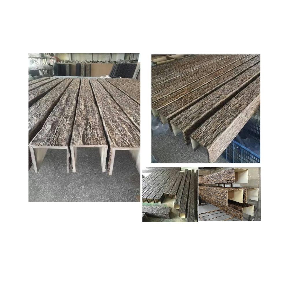
Standard three-sided hollow beams create void spaces sized primarily to accommodate mounting hardware rather than extensive electrical routing. A typical 6x6-inch residential beam might offer 4x4 inches of clear interior space after accounting for wall thickness. Larger commercial beams—8x10, 10x12, or custom sizes—provide proportionally greater interior volumes that can accommodate multiple wire runs, junction boxes, and even small transformers.
The practical usability of this interior space depends on access points and mounting configuration. Beams installed using perimeter adhesive application leave the entire length accessible for wire fishing. Systems using intermittent mounting blocks create segmented interior spaces where wiring must navigate around blocking. Understanding your mounting approach before planning electrical integration prevents discovering impossible routing scenarios during installation.
Manufacturers increasingly offer beams with molded-in wire channels—dedicated grooves or tunnels within the polyurethane structure that guide wiring away from fastener locations and create organized pathways. These channels typically run the full beam length, positioned along the back face where mounting hardware won't interfere. Wire capacity depends on channel sizing, with residential beams accommodating 2-4 circuits of standard 14 or 12-gauge wire and larger commercial beams handling substantially more.
The fire rating implications of electrical routing through beams require consideration in commercial applications. While the beam itself may carry Class A fire rating, filling it with combustible wire insulation and creating continuous pathways for flame spread might compromise that rating. Consult with manufacturers and code officials when planning extensive electrical routing through fire-rated beam systems, particularly in occupancies with stringent fire safety requirements.
Planning Electrical Integration During Design
Successful electrical integration begins during schematic design, not as a field improvisation during installation. Map fixture locations precisely, understanding which ones need power delivered through beam routing versus alternative paths. Pendant lights dropping from beam faces represent obvious candidates for beam-routed power. Track lighting, recessed fixtures, and decorative beam-mounted sconces similarly benefit from concealed routing.
The electrical load calculations determine wire sizing that impacts routing feasibility. Low-voltage LED systems using 18 or 20-gauge wire consume minimal space and route easily through even small wire channels. Full-voltage systems with multiple high-wattage fixtures may require larger conductors that challenge beam interior capacity. Dividing circuits across multiple beams, using home-run wiring to central panels, or supplementing beam routing with conventional ceiling routing solves capacity constraints.
Coordination with the electrical engineer or contractor should occur before finalizing beam specifications. Share interior dimension data, wire channel locations, and access point positions so the electrical design can account for beam capabilities and limitations. This coordination identifies conflicts early—like fixtures positioned where mounting blocks would prevent wire routing—allowing design adjustments before construction begins.
Mock-ups prove invaluable for complex electrical integration. Before ordering full beam quantities, test wire fishing and fixture mounting using sample beams. Verify that wiring reaches fixture positions, that junction boxes fit within beam interiors where planned, and that access points align with installation sequences. Problems discovered during mock-ups cost hours to solve; the same problems discovered mid-installation cost days and budget overruns.

Installation Techniques for Concealed Wiring
Wire fishing through beam interiors follows similar principles to fishing through walls, though the straight, unobstructed beam length makes the process considerably easier. Begin by securing beam mounting, then fish wires before final beam installation in cases where beams slip onto mounting ledgers. For beams that attach directly to ceilings, fishing occurs after installation through access holes at beam ends or at fixture penetration points.
The fish tape or pull wire enters at one access point and exits at another—either beam end or a fixture hole. Attach electrical conductors to the pull wire using techniques that prevent snagging during the pull-through. Electrical tape wrapping the connection point creates a smooth transition that slides through wire channels without catching on internal features. Pull steadily rather than jerking, watching for resistance that indicates binding requiring correction before damaging wires.
Junction boxes positioned within beam interiors allow multiple fixtures to home-run to a single power source rather than daisy-chaining through the beam length. Shallow "pancake" boxes sized to fit beam interior dimensions mount to blocking or directly to ceiling surfaces before beam installation. Wire routing brings power to these junction boxes, then distributes to individual fixtures. This approach reduces wire runs and simplifies troubleshooting compared to through-wiring every fixture.
Support for wiring within the beam interior prevents sagging or bunching that could interfere with beam installation or removal. Small cable clips attached to beam interior surfaces secure wiring at regular intervals. When beams include molded wire channels, wiring simply snaps into the channel grooves where it stays organized without additional support. Avoid using metal fasteners that might penetrate the beam exterior—plastic clips or foam-backed adhesive mounts protect surface integrity.
Fixture mounting through beam faces requires clean, precise penetrations that don't telegraph as afterthoughts. Layout fixture positions accurately during beam installation, drilling or cutting openings that match fixture escutcheons precisely. Oversized holes that rely on fixture canopies to hide sloppy work rarely satisfy when fixtures are viewed from varied angles. For pendant drops, drill holes perpendicular to beam faces so fixtures hang plumb rather than at awkward angles.
Fixture Types Best Suited to Beam Integration
Pendant lighting represents the most common fixture type integrated with faux beams. Single large pendants or multiple small fixtures dropping from beam centerlines create strong visual elements while leveraging beam-routed power naturally. The beam-to-pendant relationship should appear intentional—fixtures positioned rhythmically along beam lengths or concentrated at architecturally significant locations like beam ends or intersections.
Track lighting mounted to beam faces provides adjustable accent illumination without visible wiring. The track itself mounts using screws through the beam into ceiling blocking, with power entering through the beam interior at track end-feed locations. This approach works particularly well in commercial applications where lighting needs evolve over time—track heads can be repositioned or replaced without affecting concealed wiring.
Recessed can lights installed within beam cross-sections create dramatic downlighting effects while maintaining clean ceiling planes. This application requires larger beams—minimally 8x10 inches—to accommodate standard recessed can housings. The beam essentially functions as a soffit containing the lighting fixture, with power routed through the same space. Proper clearance between polyurethane and lamp heat becomes critical to prevent material damage.
Linear LED strip lighting concealed within beams creates indirect ambient illumination or accent lighting effects. Mount LED strips along beam interior faces adjacent to edges, allowing light to spill out between beam and ceiling. This detail-lighting approach emphasizes beam presence while providing useful illumination. Low-voltage LED systems simplify wiring since thin conductors route easily through even small wire channels.
Wall-washing fixtures mounted to beam sides direct light toward vertical surfaces, emphasizing texture or artwork. These applications work well where beams run parallel to walls at appropriate distances for effective wall-washing. The beam-mounted position provides ideal aiming angles while concealing both fixtures and wiring within the ceiling treatment rather than surface-mounted on walls or ceilings.

Code Compliance and Inspection Considerations
Electrical work routed through faux beams must meet the same code requirements as conventional wiring—concealment doesn't exempt installations from National Electrical Code (NEC) provisions. All connections must occur in accessible junction boxes, not buried within beam interiors. Wire splices need proper protection and accessibility for future service. Over-current protection must reflect conductor sizing and connected loads.
The accessibility requirement proves most challenging in beam-routed systems. NEC requires that junction boxes remain accessible without removing permanent finish materials. Beams themselves don't qualify as permanent since they can be removed by reversing the installation process. However, beams mechanically fastened with numerous screws present accessibility challenges that may prompt inspector questions. Beams attached using adhesive alone can be removed when necessary, though non-destructively removing adhered beams requires care and skill.
Low-voltage lighting systems—those operating at 50 volts or less—face fewer code restrictions than line-voltage installations. Class 2 circuits using approved power supplies can route through beams with minimal concern about accessibility requirements that govern line-voltage wiring. For LED pendant and accent lighting, considering low-voltage systems simplifies both installation and inspection approval.
The electrical permit and inspection process should include beam electrical integration in scope descriptions. Inspectors uncomfortable with concealed wiring in decorative elements may require documentation of access provisions, wire support methods, and fixture clearances. Proactive communication with inspectors before rough-in helps identify and resolve concerns before wiring is concealed, avoiding costly corrections after finishes are complete.
Maintenance and Future Modification Access
Long-term maintenance requires planning during initial installation. Document wire routing, junction box locations, and circuit assignments thoroughly. These records prove invaluable when troubleshooting problems years after installation when original installers have moved on and institutional knowledge has faded. Include routing documentation in project close-out materials alongside fixture schedules and panel directories.
Removability of beams becomes important if major electrical modifications are needed. Beams installed with mechanical fasteners only can be removed, modified, and reinstalled relatively easily. Beams installed with heavy adhesive application may require damage during removal—acceptable for end-of-life renovations but problematic for circuit additions mid-lifecycle. Consider removability implications when specifying attachment methods for beams containing electrical routing.
LED fixture longevity reduces maintenance requirements compared to traditional lamp technologies, but even long-lived LEDs eventually fail. Design fixture mounting and beam access so individual fixtures can be replaced without removing entire beam sections. This approach might involve end-access to wire pulls, or junction boxes positioned where beam sections join, allowing fixture removal and wire disconnection without comprehensive beam disassembly.
Future flexibility benefits from oversized wire channels and junction boxes. Installing larger channels than immediately needed accommodates future circuit additions without requiring complete rewiring. Junction boxes with unused knockouts allow future connections without relocating boxes. This planning mindset costs little during initial construction but pays substantial dividends when change orders or tenant improvements require electrical modifications years later.

Integrated wire routing transforms hollow faux beams from simple decorative elements into functional electrical infrastructure. Understanding beam interior dimensions, planning electrical integration during design, and executing installations that balance aesthetics with code compliance creates sophisticated ceiling systems that combine form and function seamlessly. The additional effort required for integrated electrical planning repays itself through cleaner installations, expanded design freedom, and long-term flexibility that accommodates evolving lighting needs without visible compromise.
Technical References
ASTM standards cited in every specification
Test Data
Lab results from internal testing program
Updated 2026
Reviewed against current product specs