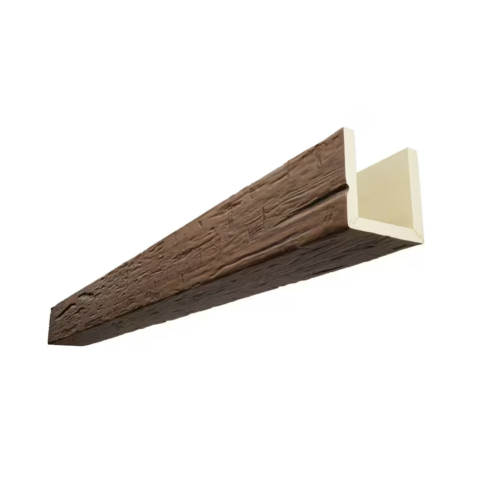
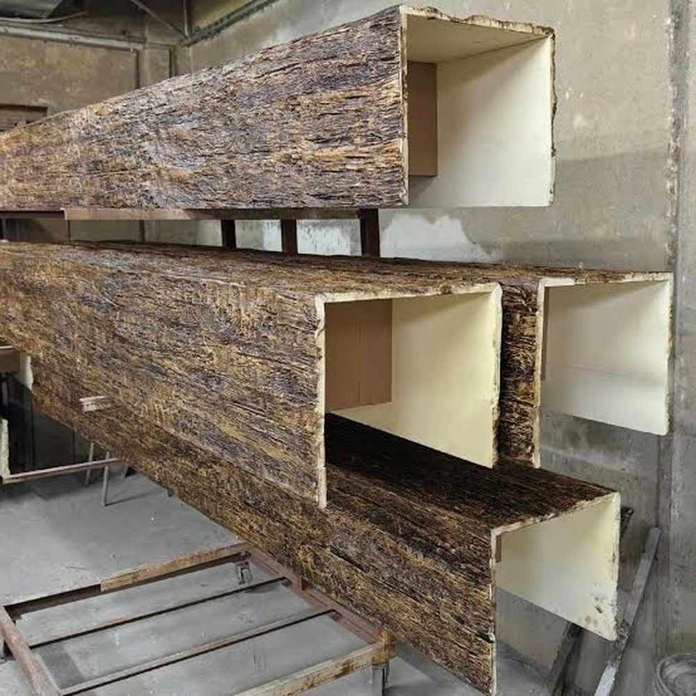
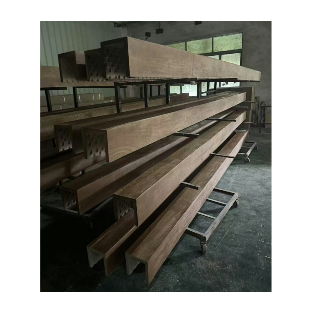
The electrical contractor installing linear LED fixtures inside decorative ceiling beams for an upscale steakhouse discovered a critical compatibility issue during rough-in: the specified fixtures—each weighing 18 pounds—exceeded the load capacity that the beam's thin polyurethane walls could safely support using the mounting clips provided. The interior designer had envisioned dramatic uplighting effects with fixtures concealed within beam cavities, washing light across ceiling surfaces while maintaining clean beam sightlines below. However, the 8-inch-deep beams specified for the project used 3/8-inch wall thickness optimized for minimal weight rather than interior load capacity. Installing eighteen fixtures as planned using standard mounting clips that bore directly against beam walls would create concentrated stress points likely to cause progressive deformation, eventually allowing fixtures to sag visibly or pull free entirely. The solution required engineering supplemental mounting channels spanning beam interiors to distribute fixture loads to beam ends where they could transfer to ceiling structure, adding $4,200 in materials and labor beyond the original lighting budget.
Lighting fixture weight compatibility with hollow beam interior spaces addresses a technical challenge that arises when designers seek to integrate functional lighting elements within decorative architectural features. The hollow three-sided configuration that makes polyurethane faux beams practical for installation—lightweight, economical, and easy to handle—creates interior cavities that appear suitable for concealing lighting fixtures, wiring, and other building systems. However, the thin-walled construction optimized for spanning as decorative elements may lack the structural capacity to support concentrated loads that lighting fixtures impose at their mounting points. Understanding beam structural characteristics, fixture load requirements, and appropriate mounting methodologies enables successful lighting integration that functions reliably throughout its service life without visible distortion or mounting failure.
Hollow Beam Structural Characteristics
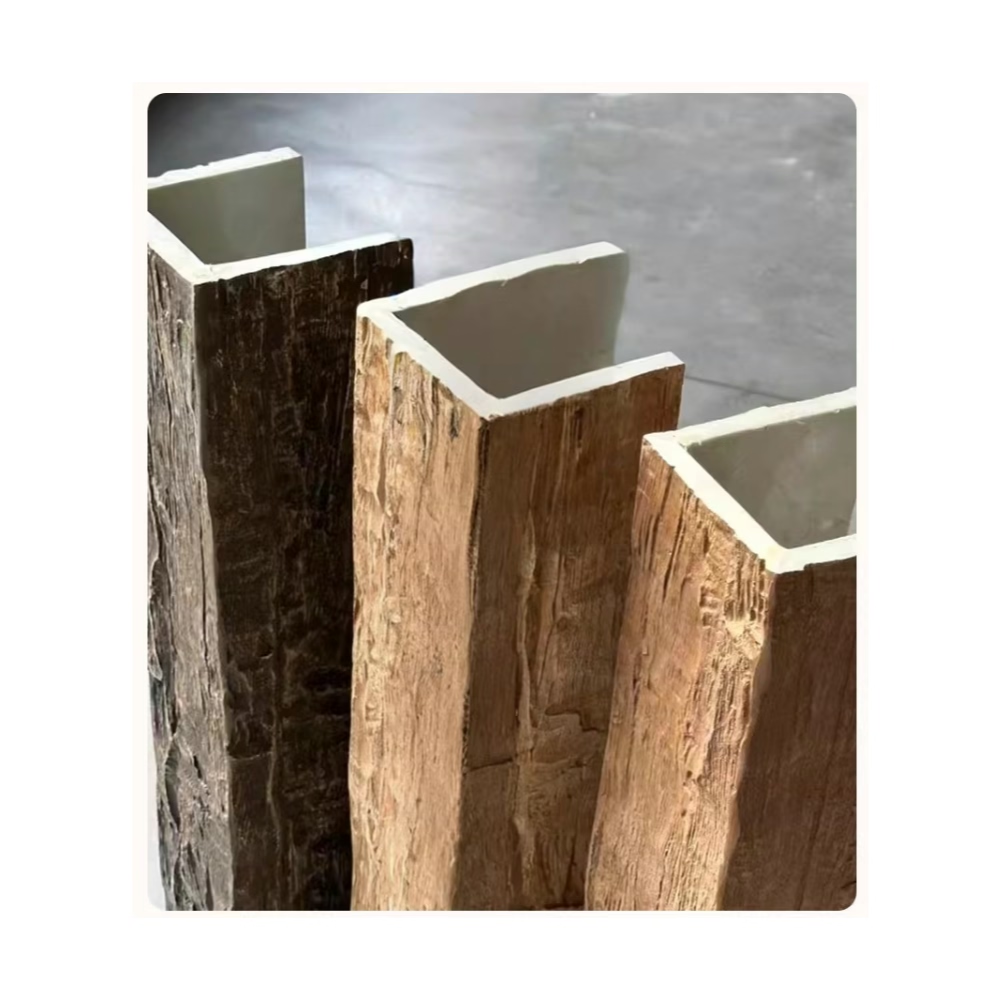
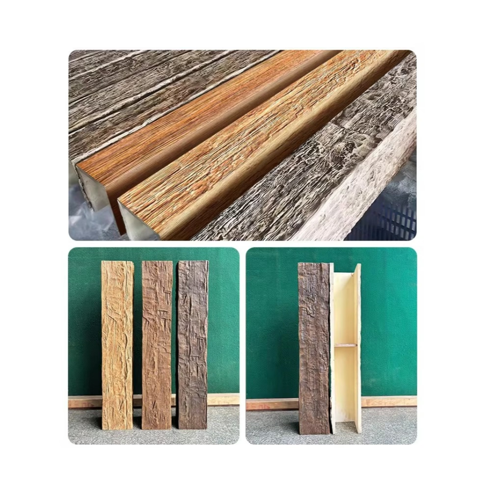
Polyurethane faux beams employ hollow three-sided configurations that provide the visual appearance of solid wood beams while eliminating the weight and cost that solid construction would require. Understanding the structural properties of these hollow sections is essential for evaluating their capacity to support interior-mounted fixtures.
Wall thickness in standard faux beam products typically ranges from 3/8 inch to 5/8 inch depending on beam size and manufacturer. Smaller beams (6 to 8-inch nominal dimensions) commonly use thinner walls to minimize weight and material cost. Larger beams (10 to 12-inch and above) may employ thicker walls to provide adequate rigidity for handling and installation across longer spans. Wall thickness directly affects both the beam's bending stiffness—its resistance to deflection when supported at ends and loaded along its length—and its local bearing strength at concentrated load points.
Material properties of polyurethane foam used in beam manufacturing determine load-bearing capacity for any given wall thickness. Polyurethane density typically ranges from 3 to 6 pounds per cubic foot for decorative beam applications, with higher densities providing greater strength and stiffness but also increased weight and cost. The specific polyurethane formulation affects compressive strength (resistance to crushing under concentrated loads), tensile strength (resistance to pulling apart), and creep resistance (tendency to deform progressively under sustained loads). Most beam manufacturers do not publish detailed structural properties because beams are intended as decorative elements rather than structural members, leaving designers and contractors without clear guidance about load capacities.
Cross-sectional geometry affects how beams respond to loads applied to interior surfaces. The three-sided U-shape creates an open section with limited torsional rigidity—if loads apply asymmetrically or tend to twist the section, the open configuration provides little resistance. The parallel side walls act structurally as thin plates supported only at their edges (top edge where walls meet ceiling, and ends where walls close at beam terminations). Concentrated loads applied to these unsupported wall areas create localized bending that thin sections resist poorly.
Span length between supports influences beam capacity to resist interior loads. A beam supported only at its ends—the typical installation configuration—experiences maximum deflection at mid-span under uniform or concentrated loads. Interior-mounted fixtures positioned at mid-span impose loads at the location where beam deflection tendency is greatest. Shorter beam spans provide better load resistance than longer spans of identical cross-section. Intermediate supports, if provided through blocking or other structure penetrating beam cavities, dramatically improve load capacity by reducing effective span.
Lighting Fixture Load Characteristics
Lighting fixtures proposed for beam interior mounting impose loads through several mechanisms that must be evaluated against beam capacity.
Dead weight of fixtures and associated components represents the primary load. Light fixtures range enormously in weight depending on type, size, and construction. Compact LED strip fixtures designed for cove lighting might weigh under 2 pounds per foot. Linear fluorescent or LED fixtures in commercial configurations might weigh 8 to 15 pounds for 4-foot lengths. Larger fixtures or those incorporating substantial housings, ballasts, or LED drivers can exceed 20 pounds. Transformers, junction boxes, and other electrical components add to total dead load. Accurate load assessment requires weighing actual specified products rather than estimating from general fixture categories.
Dynamic loads during installation, maintenance, or accidental contact can momentarily exceed static dead weight substantially. Installers dropping fixtures the final inches into mounting brackets create impact loads potentially several times static weight. Maintenance personnel pulling down on fixtures to access connections or adjust positions apply loads that mounting systems must resist. These dynamic effects typically receive less engineering attention than dead loads but can cause mounting failures, particularly in marginally adequate installations where static loads nearly exhaust available capacity.
Load distribution to mounting points depends on fixture configuration and mounting method. A fixture mounted at three or four points along its length distributes total weight among those locations, reducing load at any single point. Fixtures hanging from single-point suspensions concentrate full weight plus any dynamic factors at one location. The geometry of mounting brackets affects stress distribution within beam walls—clips bearing against walls over small areas create high concentrated stress, while brackets distributing loads over larger wall areas reduce local stress intensity.
Sustained loading over years or decades can cause progressive deformation through creep even when initial installation appears adequate. Polyurethane foams under constant stress gradually deform, potentially allowing fixtures to sag over time even though they showed no immediate distress after installation. Creep effects depend on material formulation, stress intensity, and environmental conditions including temperature. Manufacturers rarely provide creep data for decorative beam products, making long-term performance somewhat uncertain for loading scenarios not extensively proven in practice.
Mounting Method Options
Several mounting methodologies can attach lighting fixtures inside hollow beam cavities, each with distinct load capacity characteristics and installation requirements.
Direct bearing clips or brackets that attach to beam interior walls represent the simplest mounting approach. These clips fasten to wall surfaces using screws driven into polyurethane, then support fixtures through mechanical interference or clips. Load capacity depends entirely on local bearing strength of beam walls and pullout resistance of mounting screws. This method works reliably only for very lightweight fixtures (under 5 pounds total) and when stress distributes over adequate wall area. Mounting multiple small clips rather than few large ones distributes stress more evenly, improving reliability.
Through-bolted connections penetrate beam walls entirely, using bolts with washers on both interior and exterior surfaces. This configuration improves load capacity by creating bearing on both wall faces rather than depending solely on screw pullout resistance. Through-bolting visibly marks beam exteriors with bolt heads or caps, potentially compromising appearance unless bolt locations are carefully positioned or concealed. Structural capacity of through-bolted connections depends on bolt bearing area, washer size, and whether washers are large enough to prevent localized crushing of polyurethane foam. Through-bolting provides the strongest direct-to-wall attachment method but remains limited by wall thickness and material strength.
Supplemental mounting channels spanning beam interiors provide structural members independent of beam walls to carry fixture loads. Steel channels (C-channels, angle iron, or tube sections) span from beam end to beam end, supporting fixtures along their length while transferring loads to beam ends where connection to ceiling structure can occur. This approach completely bypasses load-bearing demands on beam walls, allowing mounting fixtures of essentially any practical weight. Installation complexity increases because channels must be sized and installed, requiring advance planning and sometimes necessitating installing channels before beams themselves. Channel weight adds to overall beam assembly weight, potentially requiring larger mounting cleats or additional adhesive for beam attachment to ceilings.
Hybrid systems combining direct wall mounting with supplemental support optimize between simple lightweight installations and heavy-duty channel approaches. A hybrid might use light-gauge wire or cable spanning beam interiors to provide safety backup for fixtures primarily supported by wall-mounted clips, or might employ minimal channel sections only at fixture mounting locations rather than continuously. Hybrid approaches can provide adequate capacity for moderate fixture weights (8 to 12 pounds) while avoiding the expense and complexity of full channel systems.
Structural Analysis Methods
Determining whether specific beam and fixture combinations provide adequate structural capacity requires analysis ranging from simple rules-of-thumb through detailed engineering calculations.
Rule-of-thumb guidelines based on experience provide quick preliminary assessment. Conservative practice limits fixtures mounted directly to beam walls to 5 pounds maximum total weight for standard residential-grade beams (3/8-inch walls). Heavier fixtures up to 10 to 12 pounds might be acceptable with through-bolted connections using large-diameter washers to distribute bearing stress. Any fixture exceeding 12 pounds typically warrants supplemental mounting channels rather than relying on beam walls alone. These guidelines provide reasonable starting points but don't account for variations in beam quality, installation conditions, or specific load configurations.
Load calculation comparing imposed stress against material capacity provides quantitative analysis. This approach calculates stress intensity at mounting points—load divided by bearing area—and compares against polyurethane compressive strength. If calculated stress remains below a reasonable fraction of material strength (typically 25% to 33% to account for uncertainty and provide safety margin), the mounting should perform adequately. Limitations include uncertainty about actual material properties if manufacturer data is unavailable, and difficulty predicting stress distribution accurately for complex mounting geometries.
Finite element analysis (FEA) using structural analysis software can model beam sections under specific loading, predicting stress distribution and deflection patterns throughout the structure. FEA requires creating computer models of beam geometry, defining material properties, applying loads and boundary conditions, then solving for structural response. This sophisticated analysis provides detailed predictions but demands expertise, software access, and time investment justifiable only for critical applications or when developing standardized solutions for repeated use.
Physical testing of representative samples provides empirical data about actual capacity. Testing involves mounting fixtures to sample beam sections using proposed methods, applying loads, and monitoring response. Testing might include static load tests incrementally increasing load until failure occurs, determining ultimate capacity and appropriate working loads. Sustained load testing applies fixture weights for extended periods (weeks or months) to evaluate creep behavior. Testing eliminates uncertainty about material properties and mounting method effectiveness but requires test facilities, time, and destructive consumption of sample materials. Testing is most practical when developing standardized mounting systems for production use rather than one-off project applications.
Design Integration Strategies
Successful lighting integration within beam cavities requires coordinating electrical, structural, and aesthetic considerations throughout design development.
Fixture selection with weight constraints prioritizes lightweight products when interior beam mounting is intended. LED lighting technology provides significant advantages because LED fixtures typically weigh substantially less than equivalent fluorescent or HID alternatives. Specifying fixtures designed specifically for weight-sensitive applications—cove lighting, under-cabinet lighting, and similar categories—often yields products weighing 50% to 70% less than standard commercial fixtures of similar light output. Weight data should be confirmed from manufacturer literature and should include all components that will mount within beams including transformers, drivers, and junction boxes.
Beam sizing to provide adequate interior mounting capacity may involve selecting larger or heavier-grade beams than aesthetic considerations alone would require. Beams specified with 1/2-inch or 5/8-inch walls rather than 3/8-inch walls provide substantially better load-bearing capacity at mounting points. Some manufacturers offer beams specifically intended for applications requiring interior mounting, with reinforced wall sections or factory-installed mounting provisions. The modest cost premium for heavier-duty beams often proves more economical than field-installing supplemental mounting structures.
Mounting point distribution along beam length reduces load concentration by spreading fixture weight among multiple attachment points. A single 12-pound linear fixture might mount adequately using four mounting points (3 pounds each) where two mounting points (6 pounds each) would be marginal. Distributing mounting points requires that fixtures provide attachment provisions at appropriate intervals, so fixture and mounting method selection must coordinate.
Load transfer detailing ensures that loads ultimately transfer to structure capable of supporting them rather than accumulating in beam assemblies. Beam ends require sufficiently robust mounting to ceiling structure to carry fixture loads in addition to beam self-weight. Ceiling blocking or structure at beam ends should be verified adequate for total loads. Where supplemental mounting channels span beam interiors, channel ends must connect positively to structure, not merely abut beam ends relying on friction or minimal fasteners.
Electrical Coordination Requirements
Integrating lighting within beam cavities involves electrical work coordinated with structural mounting considerations.
Wiring access into beam interiors requires planned pathways that don't compromise beam appearance. Common approaches include bringing wiring through beam ends (concealed behind end caps or within end wall thickness), through top beam surfaces where wiring enters from ceiling cavities above, or through side walls at locations where penetrations can be concealed or appear as intentional design details. Wiring penetrations should occur at locations where they don't interfere with mounting provisions and where polyurethane can be sealed around wiring to prevent light leakage from beam interiors.
Junction box placement for fixtures mounted within beams must satisfy electrical code requirements for accessibility while fitting within beam interior dimensions. Code requires junction boxes be accessible without removing permanent building finishes—meaning beam removal should not be necessary to access boxes. Some interpretations accept beam removal as acceptable access because beams mount with removable fasteners rather than permanent construction methods, but conservative practice provides access through removable beam end caps or other means not requiring disturbing entire beam installations. Junction box sizing must accommodate all connections required while fitting within beam interior width and height.
Thermal management considers heat generated by lighting fixtures and its impact on polyurethane beam material. LED fixtures generate less heat than legacy technologies but still produce thermal output requiring dissipation. Polyurethane foam materials have relatively low heat resistance, potentially degrading or deforming if subjected to sustained elevated temperatures. Fixture specifications should confirm that expected surface temperatures remain within ranges that polyurethane can tolerate (typically under 140°F sustained). Adequate air circulation within beam cavities through ventilation openings helps dissipate heat.
Code compliance verification ensures that installations satisfy electrical codes including NEC requirements for wiring methods, junction box accessibility, fixture listing and labeling, and any special requirements for concealed installations. Electrical inspectors may have questions about non-standard installations like beam-concealed lighting, making early consultation with the authority having jurisdiction valuable for confirming that proposed methods will receive approval.
Installation Best Practices
Proper installation techniques ensure that designed mounting systems perform as intended without damage to beams or fixtures.
Pre-installation mock-ups for critical or complex installations verify that mounting methods work as planned before proceeding with full installation. Mock-ups involve completely installing one representative beam section with all fixtures, mounting components, and electrical connections in shop conditions where access and adjustment are easier than field conditions. Mock-ups reveal any unanticipated interferences, assembly sequence problems, or performance issues while correction remains straightforward. Lessons learned from mock-ups inform efficient field installation.
Beam positioning before interior component installation simplifies access and provides better quality control. This sequence involves mounting beams to ceilings first with interior cavities empty, then installing mounting channels or brackets within positioned beams, then finally installing fixtures and completing electrical connections. Alternative sequences that attempt to complete all interior work before ceiling mounting create handling difficulties and risk damaging fixtures or connections during beam positioning.
Load testing after installation verifies mounting adequacy before putting installations into service. Simple pull-down tests applying moderate downward force to installed fixtures confirm secure mounting and provide some confidence about capacity. More thorough testing might temporarily attach calibrated weights exceeding fixture weight to verify that mounting can support loads with appropriate safety margins. Testing should occur while installers and equipment remain on site so any deficiencies can be corrected immediately.
Documentation through photographs and written records captures mounting configurations, locations of mounting points, and any special installation details. This documentation supports future maintenance, troubleshooting if issues develop, and provides liability protection by demonstrating that appropriate installation practices were followed. Documentation is particularly valuable for concealed installations where visual evidence of proper technique becomes inaccessible after completion.
Troubleshooting Common Problems
Installations sometimes develop problems despite proper planning, requiring diagnosis and correction.
Visible sagging in beams or fixtures indicates inadequate mounting capacity or mounting failure. Investigation should determine whether sagging results from fixture weight exceeding mounting capacity, mounting hardware failure (screws pulling out, clips deforming), or beam deflection under loads. Solutions might include adding supplemental mounting points to distribute loads better, reinforcing mounting with larger or more robust hardware, or installing supplemental mounting channels to support loads independently of beam walls.
Light leakage from beam interiors through unintended openings creates visual problems and indicates that beam cavities aren't adequately sealed. Common leakage locations include beam end caps, wiring entry points, and gaps where beam walls meet ceiling surfaces. Remediation involves sealing gaps with appropriate materials—foam weatherstrip, caulking, or purpose-made light seals—while maintaining ventilation adequate for fixture cooling.
Fixture alignment issues where fixtures mount crooked or misaligned relative to beams indicate mounting precision problems. Correction might involve adjusting mounting hardware positioning, shimming fixtures to achieve desired orientation, or in some cases removing and reinstalling mounting components more carefully. Prevention through careful initial installation following manufacturer instructions and verifying alignment before final tightening proves easier than correction after the fact.
Heat-related problems including discoloration, distortion, or degradation of polyurethane suggest excessive fixture operating temperatures. Solutions include verifying that specified fixtures are actually installed (field substitutions sometimes introduce higher-heat alternatives), improving ventilation within beam cavities by adding ventilation openings, reducing fixture output intensity if dimming capability exists, or ultimately replacing fixtures with lower-heat alternatives. Heat problems should be addressed promptly before progressive damage compromises beam appearance or mounting integrity.
The steakhouse project described in the opening implemented supplemental mounting using 1-inch square steel tube spanning beam interiors between end blocking. Fixtures mounted to tube sections using provided clips, with tube ends through-bolted to wood blocking at beam terminations. The blocking connected through beam end walls to ceiling structure, transferring all fixture loads to structure without stressing beam walls. The solution provided ample capacity for specified fixtures plus margin for potential future fixture upgrades. Post-installation evaluation including moderate load testing confirmed robust mounting without visible beam deflection. The additional cost and complexity proved worthwhile for achieving the desired lighting effects reliably without risk of future mounting failures.
Lighting fixture weight compatibility with hollow beam interior spaces exemplifies the intersection of multiple building science disciplines—structural mechanics, electrical systems, and architectural aesthetics—that must integrate for successful installations. Projects that consider structural implications of concealed lighting during design, properly analyze load capacity, and implement appropriate mounting methods create sophisticated integrated systems that perform reliably. Those that treat beam interiors as convenient utility chases without addressing structural requirements risk mounting failures, progressive deterioration, and ultimately replacement of entire installations to correct problems that proper initial design would have prevented.
Technical References
ASTM standards cited in every specification
Test Data
Lab results from internal testing program
Updated 2026
Reviewed against current product specs