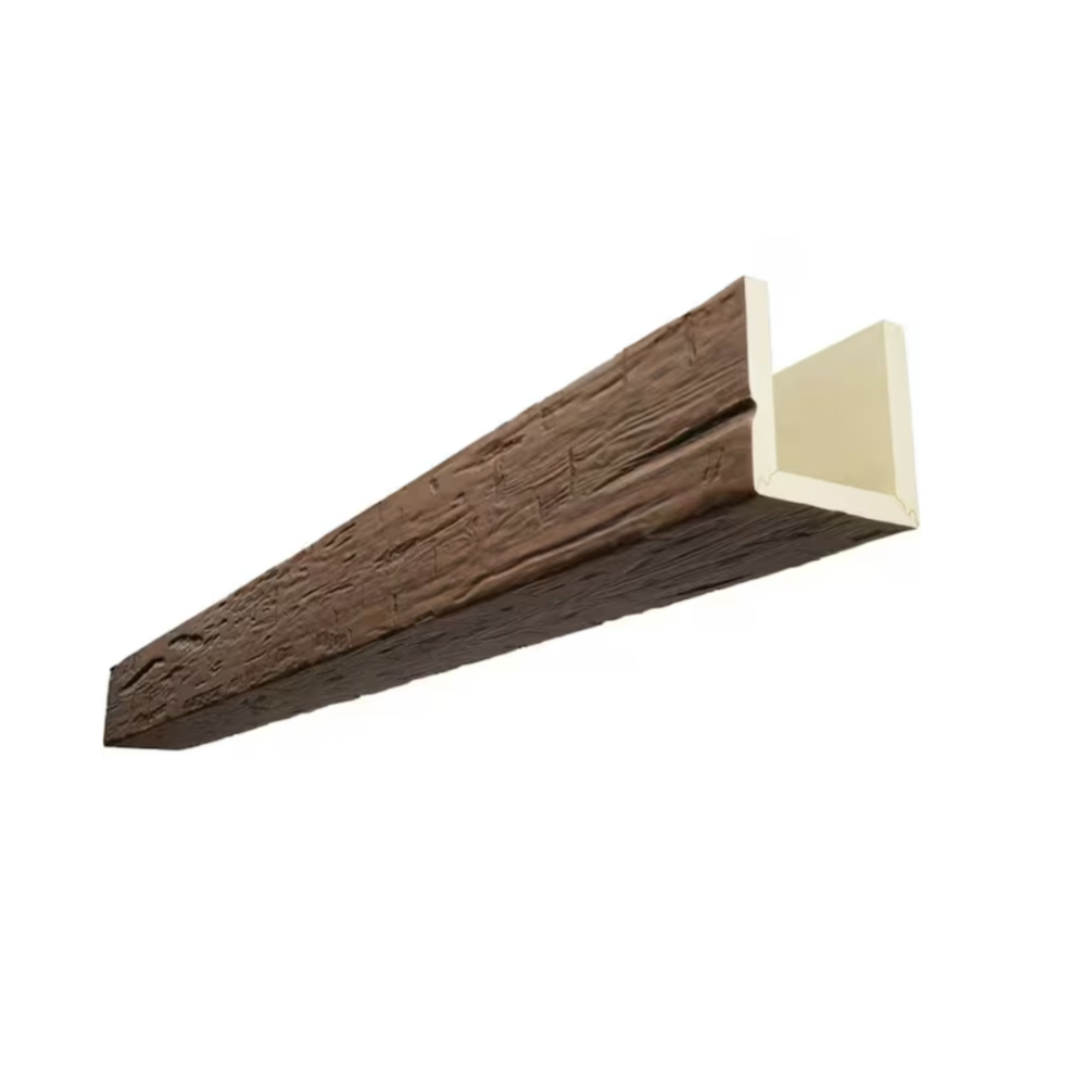
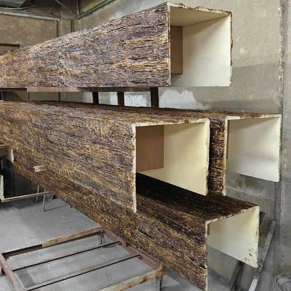
The general contractor scheduling beam installation in a 1970s-era office building renovation discovered a potentially serious structural issue three days before installation: the suspended ceiling system that would support decorative beams used lightweight 15/16-inch T-bar grid rated only for acoustic tile, not additional loads. The design documents specified attaching twenty-four substantial faux wood beams—each weighing approximately 35 pounds—to the suspended ceiling grid using toggle bolts. Had installation proceeded as specified, the combined 840-pound load distributed across the existing grid would likely have caused progressive collapse as overloaded grid members deflected and transferred loads to adjacent members until cascading failure occurred. The contractor halted work and engaged a structural engineer to assess conditions and design reinforcement. The solution required installing supplemental steel channels spanning between structure above the ceiling grid to carry beam loads independently of the existing ceiling system. The additional structural work cost $14,000 and delayed installation by two weeks, but prevented what would have been a catastrophic ceiling failure.
Load-bearing verification requirements for existing ceiling substrates address a fundamental question that retrofit beam installations must answer before proceeding: can existing structure safely support the additional loads that decorative beams will impose? This question becomes particularly critical in renovation projects where existing ceiling systems were designed for specific loads—typically just their own weight plus ceiling finishes—and may have limited or no capacity to support additional elements. Systematic verification of load-bearing capacity prevents structural failures while identifying any reinforcement necessary to safely accommodate new installations. Understanding verification methods and interpreting assessment results allows retrofit projects to proceed confidently with installations that perform safely throughout their service life.
Existing Ceiling System Types and Typical Capacities
Ceiling systems in existing buildings encompass several distinct types, each with characteristic load capacities that affect their suitability for supporting retrofit beam installations. Understanding these system types and their typical capabilities provides context for load-bearing verification.
Suspended acoustic ceiling systems using lightweight metal grid represent one of the most common existing ceiling types in commercial buildings from the 1960s forward. These systems use steel or aluminum T-shaped runners assembled into modular grids—typically 2-foot by 2-foot or 2-foot by 4-foot patterns—suspended from structure above by wire hangers at regular intervals. Acoustic ceiling tile panels rest in the grid openings, creating continuous finished ceiling surfaces. Standard grid systems for acoustic tile applications support only the tile weight plus their own weight—typically 1.5 to 2.5 pounds per square foot total. These systems have minimal capacity for additional loads. Heavy-duty suspended ceiling systems rated for loads beyond standard acoustic tile exist but are less common and must be specifically identified through documentation or physical examination.
Drywall ceiling systems attached directly to wood or steel framing provide the ceiling finish in most residential construction and much commercial work. These systems consist of gypsum board (typically 1/2 or 5/8-inch thickness) fastened with screws or nails to ceiling joists or furring. Load capacity depends primarily on framing member size, spacing, and species or gauge, plus the condition of existing fasteners and whether additional loads will be supported by drywall alone or by fasteners penetrating into framing. Properly installed drywall on adequate framing generally provides good capacity for distributed loads but requires that beam attachments fasten into framing members rather than drywall alone.
Plaster ceiling systems in older buildings use gypsum or lime plaster applied over wood or metal lath attached to ceiling framing. These traditional ceiling assemblies can be surprisingly strong—plaster typically bonds well to lath and gains some structural capacity from the composite action of multiple material layers. However, age-related deterioration including cracking, delamination, and corrosion of metal lath or rusting of fasteners can substantially reduce capacity from original conditions. Historical plaster systems require particularly careful evaluation because their condition often varies across a single ceiling.
Exposed structure ceilings in industrial, warehouse, and contemporary residential loft spaces present structure directly as the finished ceiling rather than installing separate ceiling finishes. These conditions might expose wood joists, steel beams, concrete waffle slabs, or other structural systems. Load capacity in these situations depends entirely on the existing structural members and requires structural engineering evaluation to determine what additional loads can be safely imposed.
Dead Load Versus Live Load Considerations
Structural load analysis distinguishes between dead loads—permanent, static loads that don't change—and live loads—variable loads that may be present at some times but not others. Decorative ceiling beams represent dead loads, which affects how their structural impact should be evaluated.
Dead load characteristics of ceiling beams include their predictable, unchanging nature. Once installed, a decorative beam exerts constant downward force equal to its weight distributed across whatever attachment points secure it. Polyurethane faux beams typically weigh 2 to 4 pounds per linear foot depending on size, meaning a 16-foot beam might impose 32 to 64 pounds total load. This load is permanent and fully predictable during design—unlike live loads such as wind or occupant loads that vary over time.
Cumulative dead load becomes the critical consideration when multiple beams install in a single space. Individual beam loads may appear modest—a 40-pound beam represents trivial load in structural engineering terms—but twenty beams totaling 800 pounds distributed across a ceiling system designed with minimal excess capacity could exceed safe limits. Load-bearing verification must consider cumulative effects of all planned beams rather than evaluating individual beams in isolation.
Structural codes apply different safety factors to dead loads versus live loads. Dead loads, being predictable and permanent, typically receive lower safety factor multipliers (1.2 to 1.4 in common structural codes) compared to variable live loads (1.6 to 2.0). This means that from a code perspective, a ceiling system might safely accept higher magnitude dead load from beam installations than it could accept in live loads. However, this distinction provides limited practical benefit because most ceiling systems were designed with minimal excess capacity regardless of load type.
Dynamic effects during installation can temporarily create higher loads than final static conditions. Beam installation activities—workers in ceiling spaces, temporary load concentrations during material positioning, impact loads from dropped tools or materials—may momentarily exceed final dead loads. Installation procedures should account for these effects, potentially including temporary shoring during installation if existing systems have marginal capacity even for final dead loads.

Visual Assessment Methods
Initial load-bearing evaluation typically begins with visual assessment of existing ceiling systems to understand their type, configuration, and condition. While visual assessment alone cannot definitively determine load capacity, it provides essential information for more detailed analysis.
Ceiling system identification establishes what type of structure will support beam loads. Visual inspection from below and above ceiling finishes (accessing ceiling cavity spaces where possible) identifies whether systems consist of suspended grid, drywall on framing, plaster, or other configurations. Identification includes noting specific grid types for suspended systems (standard versus heavy-duty, runner size and gauge), framing member sizes and spacing for framed systems, and plaster thickness and lath type for historic systems.
Existing condition assessment evaluates whether systems exhibit deterioration that might reduce capacity below original design. Signs of concern include sagging in suspended ceiling grid, cracked or delaminated plaster, water staining indicating past or ongoing leaks, corroded metal components in suspended systems or metal lath, and damaged or overloaded framing members showing excessive deflection or cracking. Any of these conditions suggests reduced capacity requiring either reinforcement or more conservative assumptions about allowable loads.
Loading pattern analysis considers how existing conditions distribute loads to structure. For suspended ceilings, hanger spacing and condition determines how effectively grid systems transfer loads to structure above. For framed ceilings, framing span direction and whether proposed beam locations align with framing or span between framing members affects load distribution. Understanding existing load paths helps predict how additional beam loads will be carried and whether existing capacity can accommodate them.
Documentation review provides information beyond visual inspection alone. Building plans, specifications, and structural drawings (where available) establish design criteria for existing systems. Permit records may document modifications or repairs that affect current condition. Maintenance records might reveal past problems or current concerns. For newer buildings or those with available records, documentation review significantly enhances understanding of existing capacity.
Quantitative Load Analysis
Definitive load-bearing verification requires quantitative analysis comparing imposed loads against existing structural capacity. This analysis typically requires engineering expertise but follows established methodologies.
Load calculation for proposed beam installation begins with determining total dead load that beams will impose. Each beam's weight should be confirmed—either from manufacturer data or by weighing sample pieces—and multiplied by the number of beams planned. Distribution of this load to ceiling attachment points depends on beam attachment configuration. A beam attached at four points distributes its weight approximately equally to those four locations (though not exactly equally due to load sharing effects). Total ceiling load equals the sum of individual beam loads, typically expressed as total weight and as distributed load per square foot for comparison with ceiling system capacity.
Existing capacity determination requires analyzing the load-carrying ability of ceiling systems as currently configured. For suspended ceiling systems, this involves calculating allowable loads on grid members and hanger wires based on their size, material properties, and span. For framed ceiling systems, capacity calculations follow standard structural mechanics analyzing bending stress and deflection in framing members. These calculations require information about member sizes, spans, material properties, and existing loads. Conservative engineering practice typically applies reduced material properties accounting for potential deterioration in existing structures rather than using handbook values for new materials.
Load comparison determines whether existing capacity exceeds imposed loads by adequate margins. Structural codes specify safety factors and load combinations that must be satisfied. For dead load from ceiling beams added to existing dead loads, common codes require that total load not exceed member capacity divided by safety factors—typically resulting in allowable loads around 50% to 70% of ultimate capacity. If imposed loads plus existing loads fall below this threshold, existing structure is adequate. If loads exceed the threshold, reinforcement is necessary.
Deflection analysis supplements strength analysis. Even when structures have adequate strength to prevent failure, excessive deflection under loads can cause serviceability problems—cracked finishes, misaligned elements, and visual sagging. Building codes typically limit deflection under live loads to span/240 or span/360 depending on element type and finish materials. For retrofit beam installations, similar deflection limits should be applied to ensure that beam loads don't cause visible ceiling distortion. Deflection analysis requires calculating elastic deformation of ceiling systems under imposed loads and comparing against reasonable limits.
Structural Engineering Involvement
Load-bearing verification for anything beyond simple installations typically warrants structural engineering involvement. Understanding when engineering expertise becomes necessary and what engineers can provide helps projects scope verification efforts appropriately.
Straightforward installations in known favorable conditions may proceed without engineering analysis. Lightweight beams (under 30 pounds total) installed individually at wide spacing in buildings with modern construction and good condition might reasonably proceed based on experienced contractor judgment. However, this represents a limited set of conditions—many retrofit projects fall outside these parameters and warrant engineering review.
Conditions triggering engineering involvement include moderate to heavy beam installations (multiple beams or large individual beams totaling substantial loads), installations in buildings of uncertain structural adequacy (older construction, unknown ceiling system type, visible deterioration), installations in suspended ceiling systems which typically have minimal excess capacity, and any installation where liability concerns suggest formal analysis provides valuable risk mitigation. Project teams should err toward including engineering rather than proceeding with inadequate verification.
Structural engineer scope for ceiling load verification typically includes site investigation documenting existing conditions, load analysis comparing imposed loads against available capacity, recommendations for reinforcement if existing capacity proves inadequate, and sealed letters or drawings certifying that installations will perform safely. This scope provides thorough verification while remaining manageable for the limited complexity that decorative beam installations typically involve. Engineers can usually complete this work efficiently when provided good information about proposed installations and reasonable access to existing conditions.
Cost for structural engineering services on load verification projects varies but typically represents modest investment relative to installation cost. Engineers might charge fixed fees for simple evaluations—perhaps $1,500 to $3,000 for straightforward ceiling assessments—or hourly rates for complex situations. This cost provides liability protection and verification confidence that substantially exceed the expense, particularly given the consequences if underestimated loads cause ceiling failure.
Reinforcement Strategies
When load-bearing verification determines that existing ceiling substrates lack adequate capacity for proposed beam installations, several reinforcement strategies can provide the necessary support.
Supplemental blocking between ceiling finishes and structure provides localized reinforcement at beam attachment points. This approach installs solid wood blocking or engineered lumber members spanning between structural framing members, positioned directly above each beam attachment location. Blocking distributes beam loads to structure without depending on ceiling finish materials or suspended systems to carry loads. For drywall ceiling systems with adequately sized and spaced framing, blocking represents relatively simple reinforcement accomplished by accessing ceiling cavities and installing additional framing members.
Independent support channels spanning between structure carry beam loads completely separately from existing ceiling systems. This approach installs steel channels or wood beams above existing ceilings, spanning between structural walls or framing and positioned to align with decorative beam locations below. The decorative beams attach through ceiling finishes to these support channels rather than to existing ceiling systems. This strategy works particularly well for suspended ceiling installations where existing grid systems lack capacity—support channels carry all beam loads independently without imposing any load on suspended ceilings. Installation requires accessing ceiling plenum spaces and properly connecting channels to structure.
Suspended ceiling system upgrades replace lightweight ceiling grid with heavy-duty grid rated for additional loads. Heavy-duty suspended ceiling systems using heavier gauge runners and more closely spaced hanger wires can typically support several pounds per square foot beyond standard acoustic tile loads. If beam loads remain modest and distributed relatively evenly, upgrading the entire ceiling grid provides capacity for beam installations while maintaining suspended ceiling benefits. This approach involves substantial ceiling disruption but results in a ceiling system with improved overall capacity.
Hanger reinforcement for suspended ceiling systems adds hangers or upgrades existing hangers to reduce loading on grid members. Standard suspended ceiling installations use hanger wires at 4 to 6-foot spacing. Adding supplemental hangers at closer spacing—particularly near beam attachment points—reduces spans that grid members must carry, decreasing stress and deflection. This reinforcement can be installed with minimal disruption to existing ceiling finishes by adding hangers through small access points.
Testing and Proof Loading
Some verification scenarios benefit from physical testing or proof loading to confirm that existing structures can support planned loads. These empirical approaches supplement or sometimes substitute for analytical calculations.
Pull testing of fasteners in existing substrates verifies that attachment methods will achieve required holding strength. This testing installs sample fasteners of the type planned for beam attachment and applies tension loads to verify pull-out strength. Testing multiple locations accounts for variability in substrate conditions. Results establish safe working loads for fasteners, which combined with beam weight determine required numbers and spacing of fasteners. Pull testing provides empirical data that may be more reliable than calculations when substrate conditions are uncertain or non-standard.
Proof loading applies test loads to existing ceiling systems to verify adequate strength and acceptable deflection. This approach installs temporary weights equaling or exceeding planned beam loads at proposed attachment points and monitors ceiling response. If systems support test loads without visible distress or excessive deflection, they can reasonably be expected to support actual installations. Proof loading provides direct demonstration of adequacy but requires careful procedure to avoid damage if systems prove inadequate. Testing should begin with partial loads and increment toward full loads while monitoring response.
Deflection monitoring during proof loading measures ceiling movement under loads to verify that deflection remains within acceptable limits. Deflection can be measured using precision levels, laser instruments, or simple mechanical gauges depending on required accuracy. Monitoring multiple points across ceiling areas provides information about load distribution and identifies any localized areas of concern. Measured deflection can be compared against calculated values to verify that actual behavior matches analytical predictions.
Non-destructive testing methods including ultrasonic testing, radiography, or bore-scope inspection can evaluate conditions inside ceiling assemblies when visual inspection is limited. These techniques help identify hidden deterioration, verify framing configurations, or investigate specific concerns without extensive destructive opening of finishes. Non-destructive testing typically requires specialized equipment and expertise but provides valuable information for critical situations where conventional assessment leaves significant uncertainty.
Documentation and Liability Considerations
Proper documentation of load-bearing verification protects project stakeholders from liability while providing records for future reference. Several documentation practices serve these objectives.
Engineering letters sealed by licensed professional engineers provide formal certification that installations have been evaluated and determined adequate. These letters typically describe existing conditions, summarize load analysis, present conclusions about capacity, and state that installations will perform safely when constructed as specified. Sealed engineering letters carry professional liability for the engineer's conclusions and provide strong evidence of due diligence for building owners and contractors.
Load calculations and analysis documents provide technical backup supporting engineering conclusions. Detailed calculation packages show how capacity was determined, what loads were considered, what safety factors were applied, and how conclusions were reached. These documents allow independent review and provide basis for addressing any questions that arise. Calculation documents typically remain project records rather than being submitted for permits, but their existence supports engineering certifications.
Approval for scope changes clarifies when contractors discover that conditions differ from assumptions. Load verification occurs based on available information about existing conditions, but full reality may not be apparent until ceilings are opened during installation. If actual conditions differ substantially from assumptions—different framing sizes, unexpected deterioration, modified configurations—contractors should notify engineers and obtain supplemental approval before proceeding. Documentation of this notification process protects contractors from liability for acting on superseded information.
Photographic records of existing conditions and installed reinforcement provide permanent records of work quality and site conditions. Photographs taken before, during, and after installation document what existed, what was modified or reinforced, and final configuration. These records address future questions without requiring physical investigation and can support warranty claims or dispute resolution if questions about installation arise.
The office building renovation project described at the opening implemented reinforcement using steel channels spanning between existing structure above the suspended ceiling grid. Structural engineering analysis determined that W4x13 steel channels at 8-foot spacing provided adequate capacity for planned beam loads. Channels installed perpendicular to decorative beam orientation, with beams attaching to channels through ceiling finishes using lag screws. The solution maintained existing suspended ceilings intact below while providing reliable support for beam installations above. Post-installation deflection monitoring under full loads confirmed deflections remained under L/480, well within acceptable limits. The added expense and schedule impact of supplemental structure far exceeded cost and disruption that ceiling system failure would have created, while engineering documentation provided liability protection for all project parties.
Load-bearing verification requirements for existing ceiling substrates exemplify the structural due diligence that retrofit projects require. Unlike new construction where structural systems are designed specifically for all intended loads, retrofit installations must work within constraints of existing conditions designed for different purposes. Systematic verification determines whether existing capacity suffices or whether reinforcement becomes necessary. Projects that invest in proper verification proceed confidently with installations that perform safely and reliably, while those that skip verification risk failures with consequences far exceeding verification cost.
Technical References
ASTM standards cited in every specification
Test Data
Lab results from internal testing program
Updated 2026
Reviewed against current product specs