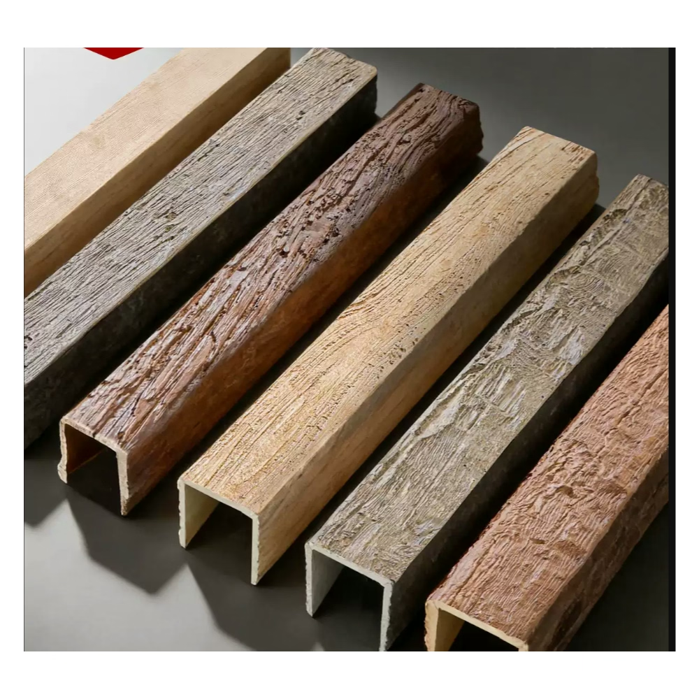
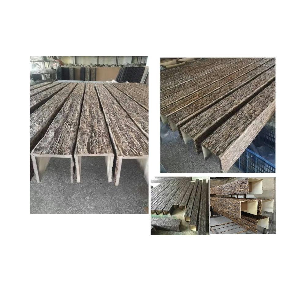
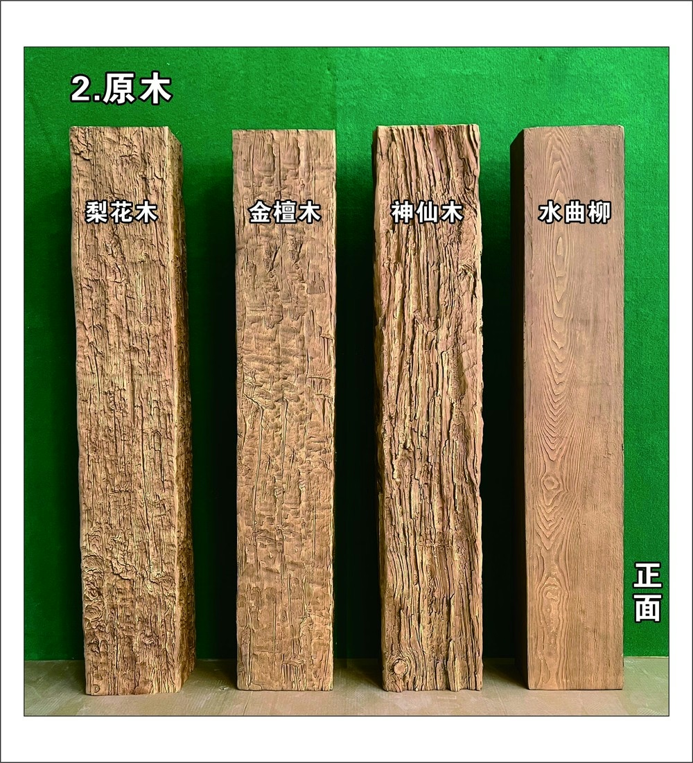
The project was nearly complete when the building inspector's question stopped us: "What's the seismic rating on these ceiling beams?" We stared blankly—the design focused on aesthetics and standard attachment methods without considering earthquake forces that could turn decorative elements into dangerous projectiles. In California's Seismic Design Category D, that oversight required complete reinstallation using rated connections. The three-week delay and $18,000 rework cost taught me that seismic requirements aren't optional considerations in earthquake country—they're fundamental design criteria that must be addressed from project inception.
Building codes in seismic zones impose specific requirements for ceiling-mounted elements, recognizing that earthquakes subject these components to forces far beyond normal gravity loads. Understanding these requirements, the attachment strategies that satisfy them, and the inspection processes that verify compliance allows designers and contractors to execute compliant installations from the start rather than discovering problems that require expensive corrections.
Understanding Seismic Design Categories and Requirements
The International Building Code classifies sites into Seismic Design Categories (SDC) A through F based on ground motion probability and soil conditions. SDC A and B represent low seismicity requiring minimal special provisions. SDC C through F reflect progressively higher seismic risk demanding increasingly stringent design and construction requirements. The west coast, Alaska, and parts of the central United States fall into higher categories where seismic provisions strongly impact construction practice.
Nonstructural components—the code classification for decorative elements like faux beams—face specific attachment and bracing requirements based on their weight, position, and failure consequences. Ceiling-mounted components located above occupied spaces present life-safety hazards if they detach and fall during earthquakes. The code's approach aims to ensure these elements remain attached during design-level ground motion, preventing injuries from falling debris.
The architectural component category under ASCE 7 Chapter 13 covers decorative beams and similar elements. The code requires attachments capable of resisting forces determined by component weight, height above grade, and component importance factor. Typical design lateral forces range from 0.3 to 1.6 times component weight depending on these factors—substantially greater than forces from gravity alone that conventional attachment methods address.
Inspection and certification requirements in high seismic zones often mandate special inspection for nonstructural component attachments. This means licensed inspectors verify attachment methods, fastener types, and installation quality before issuing approvals. Documentation proving code compliance becomes essential project records that building officials review before granting occupancy permits.
Standard Attachment Methods and Seismic Deficiencies
Typical faux beam installation using construction adhesive applied to ceiling substrates provides adequate resistance to gravity loads but proves insufficient for lateral seismic forces. Adhesive bonds perform well in shear—resisting downward gravity—but poorly in tension and peel conditions that seismic motion creates. Vibrational loading can progressively degrade adhesive bonds not designed for dynamic loading.
The lightweight advantage of polyurethane beams—typically 1-4 pounds per linear foot—reduces seismic forces compared to solid timber, but doesn't eliminate code requirements. Even lightweight components must demonstrate compliant attachment since failure consequences depend not just on component weight but on falling distances and occupancy below. A 2-pound-per-foot beam spanning 20 feet represents 40 pounds of falling hazard—enough to cause serious injury if it detaches and falls 12 feet onto someone below.
Perimeter-only attachment strategies commonly used in residential installations—where beams attach to mounting blocks at ends but span freely between—create single-point failure vulnerabilities. If one end connection fails during seismic event, the entire beam rotates around the remaining connection and can still fall. Code-compliant installations typically require distributed attachment at regular intervals ensuring redundant load paths that prevent progressive failure.
Hidden attachment methods that preserve aesthetic purity sometimes conflict with seismic requirements favoring visible, inspectable connections. Designers accustomed to concealing all fasteners behind seamless finishes must balance aesthetic preferences against code requirements and inspection practicalities. In high seismic zones, visible mechanical fasteners often prove unavoidable despite aesthetic compromises they represent.
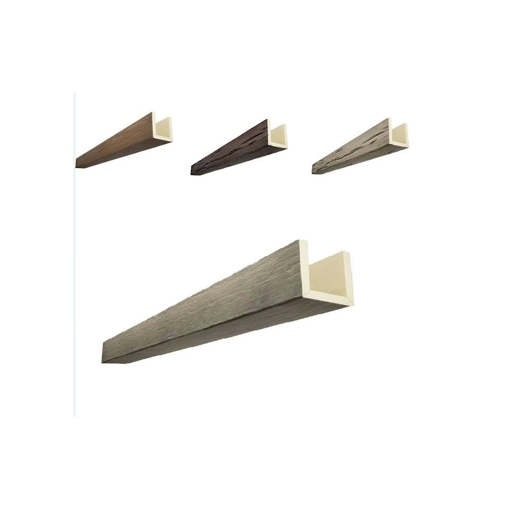
Code-Compliant Attachment Strategies
Mechanical fastener schedules designed to resist both vertical and lateral loads form the foundation of seismic-compliant beam installation. Screws or bolts penetrate through beam mounting surfaces into structural framing at spacing adequate to distribute loads. Typical spacing ranges from 16 to 24 inches on-center depending on beam weight, seismic design category, and fastener capacity. Each fastener must engage structural framing—ceiling joists, blocking, or structural deck—rather than relying on drywall or plaster alone.
Fastener selection requires attention to both tensile and shear capacity. Standard wood screws perform well in shear but offer limited tension resistance—a problem when seismic uplift forces attempt to pull beams away from ceilings. Structural screws with case-hardened threads and heads engineered for high loading provide superior performance. Lag bolts with washers offer even greater capacity for heavier beams or more severe seismic conditions, though they require pre-drilling and more complex installation.
Blocking installation between structural framing provides solid attachment points where natural framing doesn't align with beam positions. This blocking must itself be properly attached—nailed or screwed to joists or trusses with connections designed for load transfer from beam through blocking to structure. The blocking layout requires coordination during framing before ceiling finishes are applied, making early planning essential to avoiding costly access problems later.
Supplemental adhesive application remains beneficial even when mechanical fasteners provide code-required strength. Adhesive fills gaps between beam and ceiling, provides vibration dampening, and distributes stresses across broader areas than fasteners alone. The adhesive functions as secondary attachment and gap filler rather than primary structural connection—a significant distinction from standard residential installations where adhesive alone suffices.
Steel clip or bracket systems designed specifically for seismic applications offer pre-engineered solutions with documented capacity. These systems typically include steel angles or channels screwed into structural framing, with mating components attached to beams. The mechanical interlocking provides positive connection that can't peel or debond like adhesive. Manufacturers provide load ratings and installation specifications that building officials can review for code compliance without engineering calculations.
Design Considerations for Seismic Zones
Beam sizing affects seismic installation requirements substantially. Larger, heavier beams generate greater forces requiring more robust attachment. In high seismic zones, specifying the minimum beam size adequate for visual effect rather than oversizing reduces forces and simplifies compliant installation. An 8x8 beam weighing 2.5 pounds per foot generates 60% less force than a 12x12 beam at 4 pounds per foot—potentially allowing simpler attachment details.
Span length between supports influences attachment requirements since longer unsupported spans increase bending moments under lateral loading. Code calculations account for both component weight and distribution of that weight along unsupported spans. Shorter beam sections with intermediate supports reduce forces compared to long continuous spans, though the aesthetic of uninterrupted beams often drives design intent that must balance against structural reality.
Ceiling height above occupied spaces factors into force calculations through the amplification factor that increases with elevation above grade. Ground-floor ceiling beams experience lower calculated forces than identical beams on upper floors where ground motion amplifies through building response. This height effect becomes particularly significant in multi-story buildings where upper floor nonstructural requirements can exceed those at lower levels substantially.
The relationship between beams and other ceiling systems—lighting, HVAC, fire sprinklers—requires coordination in seismic installations. Beams that attach to or contact these other systems can induce failure through differential movement during earthquakes. Maintain clearances between independently supported systems, allowing each to move without interference. When penetrations must occur, use flexible connections or seismic separations preventing damage from relative motion.
Documentation and Inspection Processes
Construction documents for seismic zone projects must explicitly address beam attachment methods including fastener schedules, blocking requirements, and approved connection details. Generic notes like "install per manufacturer instructions" prove insufficient since manufacturer residential instructions typically don't address seismic requirements. The structural engineer or architect must detail specific attachment meeting code load requirements for the project's seismic category.
Shop drawings and product submittals should include load calculations demonstrating code compliance when pre-engineered systems are used. For custom installations using field-determined attachment, the design professional must provide calculations proving adequacy. Building officials increasingly require these calculations as submittal requirements before issuing permits, making them essential project documentation rather than field-developed details.
Special inspection during installation verifies that executed work matches approved details. Inspectors check fastener types, spacing, and engagement depth into structural elements. They verify blocking installation and proper connection between beams and attachment hardware. This inspection occurs before ceiling finishes conceal connections, making coordination between beam installation and finish work critical to allowing inspection access.
The documentation trail for seismic compliance typically includes approved construction documents, submittal approvals with load calculations, special inspection reports, and final inspection approvals. This paper trail becomes part of permanent building records that future owners and building officials may review during renovations or after seismic events. Maintaining organized records throughout construction prevents compliance questions that can delay occupancy or create liability concerns.
Retrofit Considerations for Existing Installations
Existing beam installations executed before current seismic codes or without proper engineering may require retrofit to satisfy modern standards, particularly in buildings undergoing substantial renovation triggering code upgrades. Assessing existing installations requires determining current attachment methods, structural framing available for improved connections, and access possibilities for installing supplemental fasteners.
Access challenges often dominate retrofit discussions since concealed connections may require removing ceiling finishes to reach existing beams from above. Cost-benefit analysis comparing retrofit expense to replacement with properly-installed new beams sometimes favors complete replacement when access costs approach new material costs. The decision factors in project scope, budget, and schedule implications of each approach.
Surface-mounted supplemental attachment hardware offers one retrofit strategy where ceiling removal proves impractical. Steel clips or brackets installed on beam faces provide additional connection points visible from below—aesthetically compromising but potentially acceptable in commercial environments where seismic safety outweighs pure aesthetic concerns. These visible connections can be painted to minimize visual impact while providing documentable structural improvement.
Engineering analysis of existing conditions determines whether retrofit proves necessary based on current code requirements and occupancy risk. Not every decorative beam installation faces retrofit requirements—the decision depends on Seismic Design Category, occupancy classification, building alterations triggering code updates, and authority-having-jurisdiction interpretation. Engage structural engineers familiar with local seismic codes and building official practices to assess specific situations accurately.

Seismic zone installation requirements for decorative beams reflect life-safety priorities that override aesthetic preferences or installation convenience. Understanding code requirements, compliant attachment strategies, and documentation processes allows designing and executing installations that keep occupants safe during earthquakes while achieving design intent. The additional cost and complexity of seismic-compliant installation proves modest compared to retrofit expenses or worse—injuries from failed installations during actual seismic events. In earthquake country, proper seismic design isn't optional expertise—it's fundamental professional responsibility.
Technical References
ASTM standards cited in every specification
Test Data
Lab results from internal testing program
Updated 2026
Reviewed against current product specs