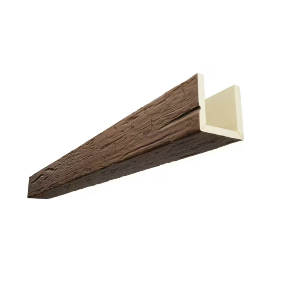
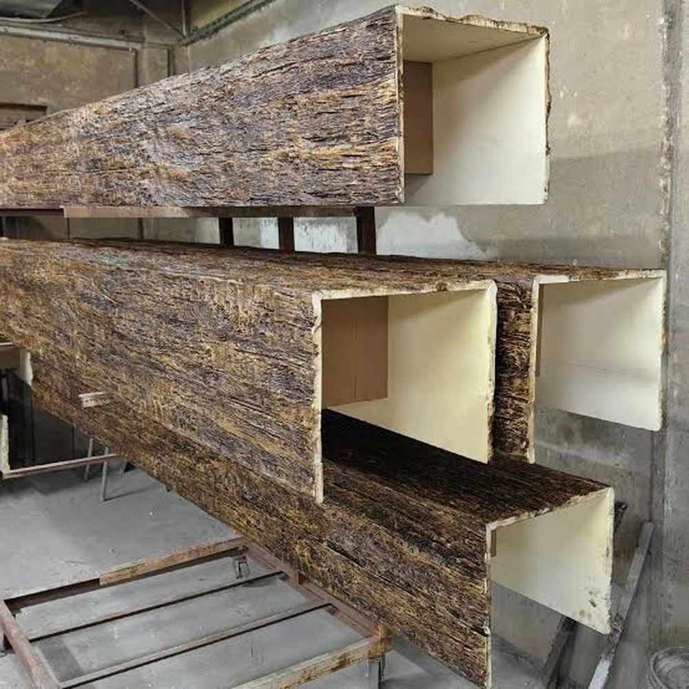
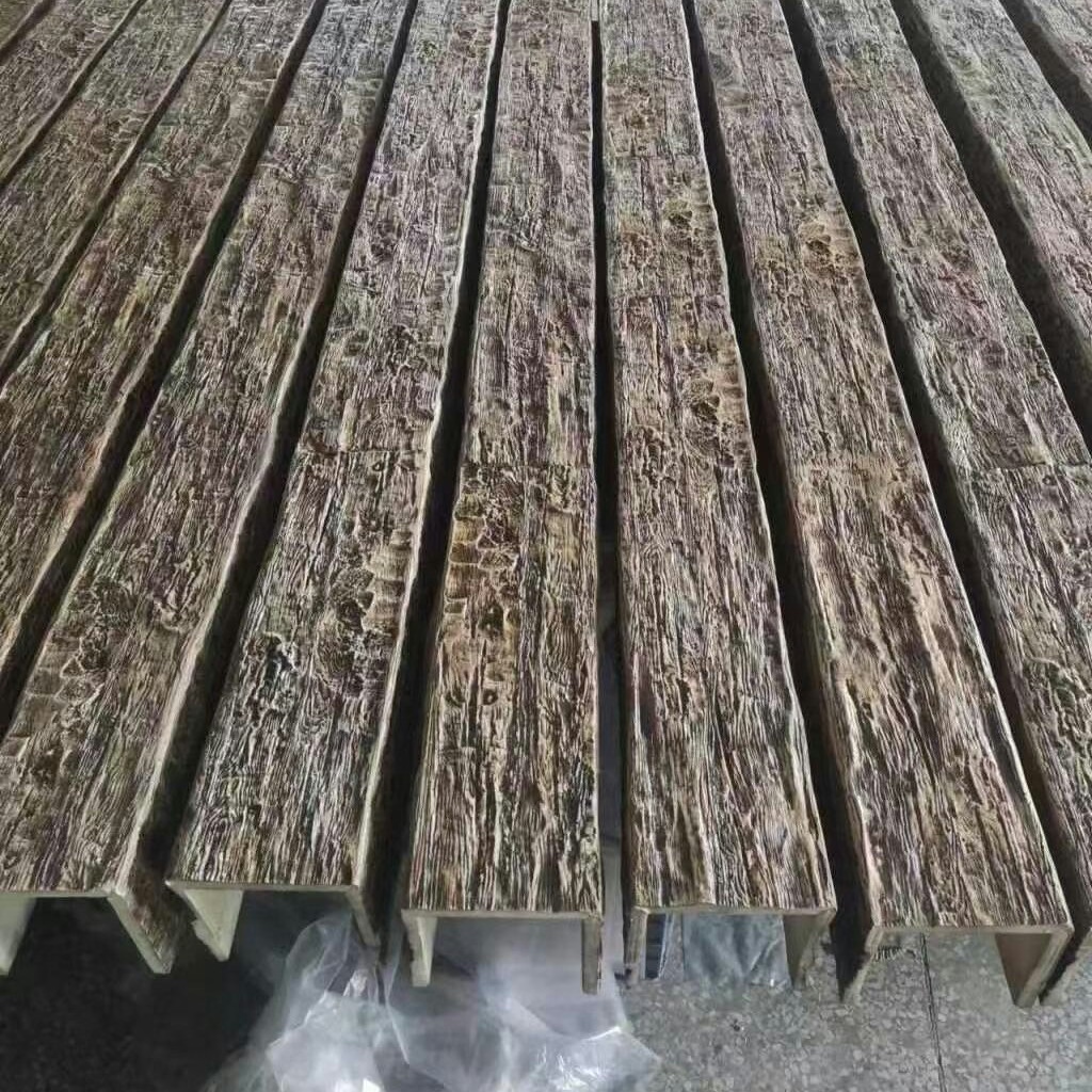
The architect approved our adhesive-only mounting proposal with one condition—we had to demonstrate through testing that bonds would reliably support beam weights plus safety factors matching those required for mechanical fastening. We developed a testing protocol using representative substrate samples, production adhesives, and installation techniques our crews would use in the field. The tests revealed bond strengths exceeding 450 pounds per linear foot—more than ten times the actual beam weight. That data satisfied the architect while giving us confidence that our installation approach would succeed. The testing investment of $3,000 proved trivial compared to the installation efficiency gains from eliminating visible fasteners.
Tensile strength testing quantifies how much perpendicular force adhesive bonds can resist before failure. For ceiling-mounted beams, this testing addresses the fundamental question: will adhesive bonds support beam weight indefinitely without detachment? Understanding testing methodologies, interpreting results, and establishing acceptance criteria allows contractors and specifiers to make informed decisions about when adhesive-only mounting proves adequate versus requiring mechanical fastener backup.
Understanding Tensile Stress in Ceiling Applications
Gravitational loading creates constant tensile stress on adhesive bonds holding beams to ceilings. Unlike shear stress from lateral forces, tensile stress acts perpendicular to bonded surfaces, pulling them directly apart. This stress type particularly challenges adhesive bonds because it concentrates stress at the adhesive-substrate interface where bonds are weakest. Understanding stress types helps explain why adhesive selection and surface preparation affect performance so dramatically.
Static versus dynamic loading distinguishes between constant weight support and impact or vibration forces. Ceiling beams experience primarily static loading from their own weight, but building vibration, seismic activity, or impact from maintenance work create dynamic loads that can exceed static loads substantially. Comprehensive testing should address both load types, though static loading typically governs ceiling applications.
Load distribution across bonded area affects stress intensity. Total beam weight divides across the bonded surface area, creating stress measured in pounds per square inch. Larger bonded areas reduce stress intensity for equivalent weights. This relationship explains why continuous adhesive beads along beam lengths prove superior to spot bonding—greater area reduces stress even though total applied load remains identical.
Safety factors multiply actual anticipated loads by margins accounting for variability, degradation over time, and unexpected conditions. Engineering practice typically applies 3x to 5x safety factors to working loads. If beams weigh 4 pounds per linear foot, adhesive systems should demonstrate 12-20 pounds per foot capacity minimum. More demanding applications or conservative design approaches might require higher safety factors.
Failure modes fall into three categories: adhesive failure at substrate interface, cohesive failure within adhesive mass, or substrate failure where substrate material tears away with adhesive still attached. Optimal adhesive systems fail cohesively—the adhesive itself tears before interface bonds fail. Substrate failures indicate weak substrates requiring reinforcement. Adhesive failures suggest inadequate surface preparation or incompatible material pairing.
Testing Methodology Development
Specimen preparation replicating field conditions ensures testing relevance to actual installations. Test specimens should use identical substrates, adhesives, application methods, and cure conditions as field installations. Testing on ideal laboratory samples under perfect conditions might not predict performance when installers apply adhesive to dusty ceilings in cold warehouses. Representative sampling provides confidence that test results translate to field reality.
Substrate selection matching project-specific ceiling types proves critical since substrate characteristics profoundly affect bond performance. Drywall, plaster, concrete, and wood substrates each exhibit different surface energies, porosity, and strength. Testing should use actual ceiling materials when possible rather than idealized substrates that might perform differently than project-specific conditions.
Surface preparation standardization documents cleaning, abrading, priming, and other preparation steps that specimens receive. Variation in preparation between specimens introduces variables that complicate result interpretation. Standardized preparation following documented protocols creates consistent baseline conditions allowing valid comparison between different adhesive systems or application parameters.
Cure conditions including temperature, humidity, and time dramatically affect bond strength development. Adhesives curing at 70°F and 50% RH develop different ultimate strengths than those curing at 50°F and 80% RH. Testing should either replicate expected field conditions or vary conditions systematically to understand environmental effects on performance. This understanding allows adjusting installation protocols for actual conditions or establishing acceptable condition windows.
Sample size determination balances statistical validity against testing costs. Engineering testing standards typically require minimum three specimens per condition tested, though five to ten specimens provide more reliable statistics. For simple go/no-go testing verifying adequate strength, three to five specimens suffice. For comparing multiple adhesive systems or developing complete understanding of system capabilities, ten or more specimens per variable condition might be justified.

Testing Equipment and Procedures
Universal testing machines providing controlled, measurable loading represent gold-standard tensile testing equipment. These computer-controlled devices apply loads at specified rates while continuously measuring force and displacement until failure. Data output includes ultimate load at failure, load-displacement curves characterizing bond stiffness, and failure mode observations. While expensive, these machines provide comprehensive data supporting engineering analysis.
Manual pull testing using calibrated spring scales or hydraulic gauges offers practical alternatives when universal testing machines aren't available or when costs exceed budgets. Manual testing provides ultimate load data though not continuous load-displacement curves. Careful technique maintains validity—steady load application avoiding shock loading, perpendicular pull orientation, and witnessed testing by qualified personnel ensure credible results.
Specimen mounting approaches must transfer test loads uniformly across bonded areas without introducing stress concentrations that would skew results. Purpose-designed fixtures attach to beam surfaces distributing pull forces evenly. Improvised mounting creating point loads rather than distributed forces produces artificially low failure loads that don't represent actual system performance. Proper fixture design proves as important as testing itself.
Loading rate specifications standardize force application speed affecting measured strength. Rapid loading produces higher apparent strengths than slow loading because viscoelastic materials stiffen under high strain rates. Standard testing typically applies loads at 0.5 to 2.0 inches per minute deflection rate. Specifying loading rates allows valid comparison between tests and ensures results represent static load capacity rather than impact resistance.
Measurement accuracy requirements depend on testing purpose. Research-grade testing might require load measurements accurate to ±0.5% using calibrated load cells and data acquisition systems. Practical field verification might accept ±5% accuracy using quality handheld equipment. Understanding accuracy requirements prevents over-investing in precision that doesn't add value while avoiding inadequate measurement that produces meaningless results.
Interpreting Test Results
Peak load values indicate maximum force bonds withstand before failure. This single number provides go/no-go assessment against acceptance criteria. However, peak loads alone don't reveal complete performance pictures—bonds might fail suddenly in brittle fashion or gradually with ductile behavior providing warning before complete failure. Comprehensive analysis considers failure behavior not just peak strength.
Load-displacement curves plot applied force versus deflection throughout testing, revealing bond stiffness and failure behavior. Steep curves indicate stiff bonds resisting deflection. Gradual curves show flexible bonds deforming substantially under load. Brittle failures exhibit sudden load drops while ductile failures show gradual load reduction after peak. These characteristics affect how adhesive systems perform in service beyond just ultimate strength.
Statistical analysis of multiple specimen results determines mean strength, standard deviation, and confidence intervals. Adhesive systems exhibiting low variability perform predictably—all specimens fail near mean strength. High variability indicates inconsistent performance where some specimens fail well below average. Design values should use mean minus two standard deviations ensuring that 95% of installations exceed design capacity.
Failure mode analysis determines whether failures occurred adhesively, cohesively, or through substrate failure. Consistent failure modes across specimens suggest systematic behavior. Mixed failure modes indicate borderline performance where small variations tip failure mechanisms between modes. Substrate failures suggest that adhesive capacity exceeds substrate strength—either acceptable if substrate matches field conditions or problematic if test substrates prove stronger than actual ceilings.
Environmental effects revealed through testing under varied temperature and humidity conditions establish acceptable installation windows and long-term performance expectations. Adhesives showing minimal strength variation across wide environmental ranges provide flexibility for installation scheduling and confidence in long-term performance. Materials exhibiting dramatic strength changes with conditions require controlled installation environments and might not suit applications with temperature or humidity extremes.
Establishing Acceptance Criteria
Minimum safety factors based on engineering judgment balance reliability against economy. Conservative approaches might require adhesive capacity of 10x actual loads. More aggressive designs might accept 3x factors when comprehensive testing, quality control, and redundancy exist. The appropriate factor depends on failure consequences, quality control confidence, and design philosophy. Life safety applications justify higher factors than purely aesthetic installations.
Code compliance verification ensures that tested capacities meet or exceed code-required values when regulations govern adhesive mounting. Some building codes prohibit adhesive-only mounting for overhead applications regardless of tested capacity. Others allow adhesive mounting when engineering analysis demonstrates adequate capacity with appropriate safety factors. Understanding jurisdictional requirements guides testing scope and acceptance criteria development.
Load duration effects address whether long-term static loading affects capacity differently than short-term test loads. Creep—gradual deformation under sustained load—can cause failures months or years after installation despite adequate short-term strength. Accelerated aging testing or sustained load testing over weeks evaluates long-term performance. Conservative design accounts for potential strength degradation even without long-term testing.
Temperature effects on bond strength require consideration for applications experiencing temperature variations. Adhesive strength typically decreases at elevated temperatures and increases at low temperatures. Testing at maximum anticipated service temperatures establishes worst-case strength. Alternatively, applying derating factors to room-temperature test results accounts for temperature effects based on manufacturer data.
Quality Assurance Testing Programs
Production testing protocols established during installations provide ongoing verification that field work achieves laboratory-predicted performance. Creating test specimens using actual job site conditions—substrate samples, field-applied adhesive, actual cure environments—allows testing specimens after cure periods matching beam installation. Results validating adequate strength confirm quality while identifying problems before extensive installation occurs.
Sampling strategies determining how many specimens to test per project or per time period balance assurance value against testing costs. Large projects might justify testing multiple specimens from different installation days verifying consistency. Small projects might test single specimens providing spot-check verification. Statistically-based sampling plans following ANSI/ASQ standards provide rigorous frameworks for quality assurance programs.
Non-conformance procedures defining responses when test specimens fail to meet acceptance criteria prevent proceeding with questionable installations. Procedures might require investigating causes, implementing corrective actions, retesting before proceeding, or inspecting previously completed work. Clear protocols established before testing prevent disputes about appropriate responses to failed tests.
Documentation requirements capture test conditions, results, and interpretations creating records supporting quality claims and providing liability protection. Test reports should include specimen preparation details, test parameters, raw data, statistical analysis, failure mode observations, and conclusion statements about whether results meet acceptance criteria. Photographs of specimens before and after testing provide valuable supporting information.
Field Verification Techniques
Pull testing installed beams confirms actual field bond strength though it inevitably damages tested areas. Attaching mechanical grips to beam surfaces and pulling perpendicular to ceilings until failure provides direct measurement of actual achieved bond strength. Destructive testing limits application to sample areas or situations where cosmetic damage proves acceptable. Some specifications require destructive testing of sacrificial beams as field verification.
Non-destructive proof loading applies loads below failure thresholds verifying minimum capacity without destroying bonds. Loading beams to 1.5x to 2x their weight verifies bonds exceed working loads without risking failure. This approach provides quality assurance value without requiring repairs to tested areas. However, proof loading doesn't reveal ultimate capacity—only that capacity exceeds proof load.
Peel testing evaluating edge bond quality provides qualitative assessment without sophisticated equipment. Attempting to insert thin blades between beam edges and ceilings reveals whether perimeter bonds remain tight. Well-bonded installations resist blade insertion while poorly bonded areas allow easy penetration. While not quantitative, peel testing quickly identifies obvious bonding deficiencies.
Acoustic testing tapping beams and listening for hollow sounds indicating unbonded areas provides rapid screening across large installations. Bonded areas produce solid, dull sounds while voids create hollow, ringing tones. Experienced installers develop sensitivity to acoustic differences detecting problems that visual inspection misses. This technique identifies gross defects though not subtle variations in bond quality.
Thermal imaging detecting temperature variations that indicate voids or delamination provides non-contact assessment of large ceiling areas. Unbonded areas exhibit different thermal mass than bonded regions, creating detectable temperature differences under appropriate conditions. While requiring specialized equipment and trained operators, thermography can scan extensive areas quickly identifying suspect regions deserving detailed examination.
Adhesive-Specific Considerations
Polyurethane adhesive behavior including foaming during cure affects test specimen preparation and result interpretation. Foam expansion fills gaps improving mechanical interlocking but creating non-uniform bondline thickness that varies between specimens. Testing should accommodate this characteristic rather than treating it as defect. Bondline thickness measurements and noting expansion behavior helps explain result variations between specimens.
Hybrid polymer adhesives exhibiting different cure characteristics and ultimate properties than polyurethanes require test protocol adjustments. These materials generally cure faster, foam less, and exhibit different stiffness and elongation properties. Testing approaches developed for polyurethane might not translate directly to hybrid polymers. Consulting adhesive manufacturer technical support ensures appropriate testing for specific material types.
Epoxy adhesive testing addresses materials offering maximum strength and rigidity but limited elongation compared to polyurethanes. Epoxies typically exhibit brittle failure modes and temperature sensitivity requiring testing protocols emphasizing these characteristics. Two-part mixing ratios must be controlled precisely since off-ratio mixtures dramatically affect cured properties.
Construction adhesive variations within this broad category perform dramatically differently despite generic labeling. Some "construction adhesives" provide adequate ceiling beam bonding while others fail catastrophically. Testing specific products rather than assuming category equivalence proves essential. Brand substitution without testing verification creates risk that actual performance doesn't match assumptions.
Comparing Test Results to Field Performance
Load factors translating test specimen results to full-scale beam installations account for scale effects and installation variability. Laboratory specimens prepared carefully under controlled conditions might outperform typical field installations. Applying reduction factors—perhaps 0.7x to 0.8x—to laboratory results provides conservative field predictions accounting for less-than-ideal real-world conditions.
Long-term performance correlation between short-duration testing and decades-long service lives requires judgment since accelerated testing incompletely predicts real-time aging. Conservative design accounts for potential degradation even without testing directly measuring long-term effects. Field inspection programs monitoring installed beam condition over years provide feedback validating design assumptions or revealing need for adjustments.
Environmental exposure differences between testing and service conditions might affect performance. Testing at room temperature doesn't predict performance in unconditioned spaces experiencing temperature extremes. Testing in moderate humidity doesn't address performance in humid coastal environments or arid desert conditions. Identifying critical environmental factors and testing under representative conditions improves predictions.
Installation workmanship variations mean that field installations might not replicate specimen preparation quality achieved in laboratories. Training, supervision, and quality control programs reduce workmanship variability though never eliminate it completely. Designing for anticipated workmanship realities rather than assuming perfect execution creates robust systems tolerating normal variability.
Economic Analysis of Testing Requirements
Testing costs including equipment, materials, labor, and analysis must be justified against project values and risk exposure. A $500,000 project might easily justify $5,000 testing investment providing confidence that installations will succeed. A $2,000 residential project can't support comparable testing costs—either accepting higher risk, using proven systems without project-specific testing, or incorporating mechanical fastener backup eliminating reliance on adhesive-only capacity.
Risk-based testing decisions balance failure probabilities, failure consequences, and mitigation costs determining optimal testing investments. High-stakes projects with severe failure consequences justify extensive testing. Low-risk applications with minimal failure consequences might proceed with minimal testing relying on manufacturer data and proven track records. Quantitative risk analysis frameworks provide structured decision-making when risk tolerances aren't obvious.
Value engineering considerations weigh testing costs against alternative approaches including mechanical fastening, hybrid systems, or more expensive proven adhesive systems. Sometimes investing in premium adhesives with extensive manufacturer testing proves more economical than conducting project-specific testing of budget adhesives. These trade-offs depend on project specifics and material cost differences.
Professional Standards and Best Practices
Industry testing standards including ASTM methods provide established protocols eliminating need to develop custom procedures. ASTM D897 covers tensile strength of adhesive bonds though designed primarily for lap-shear specimens rather than ceiling applications. Adapting standard methods to ceiling-specific conditions while maintaining standard principles provides credible testing frameworks.
Third-party testing by independent laboratories provides credibility exceeding manufacturer or contractor self-testing. While more expensive, independent testing results carry weight with architects, building officials, and in litigation that self-generated data can't match. Major projects or novel applications justify third-party testing investments.
For installers, specifiers, and contractors working on projects where adhesive-only mounting must be validated through testing rather than accepted on faith or manufacturer claims, understanding tensile strength testing methodologies, acceptance criteria, and result interpretation provides essential technical capabilities. Testing transforms mounting method decisions from guesswork into engineering supported by data. The investment in proper testing returns value through confident installations performing reliably across decades of service life while avoiding failures that destroy reputations and generate costly rework.
Technical References
ASTM standards cited in every specification
Test Data
Lab results from internal testing program
Updated 2026
Reviewed against current product specs