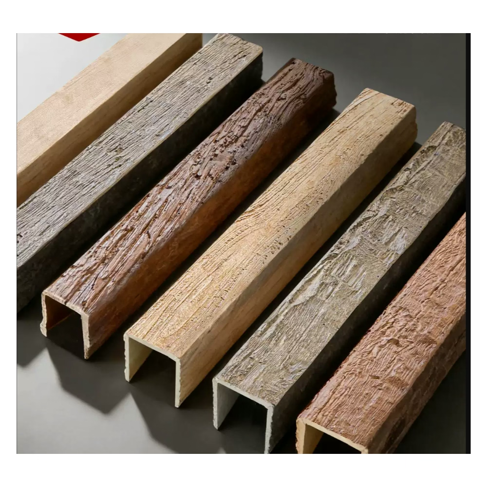
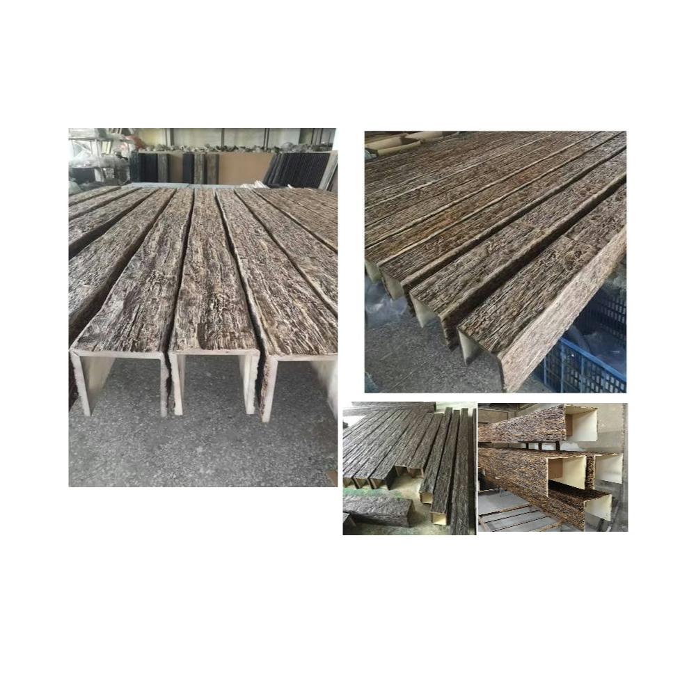
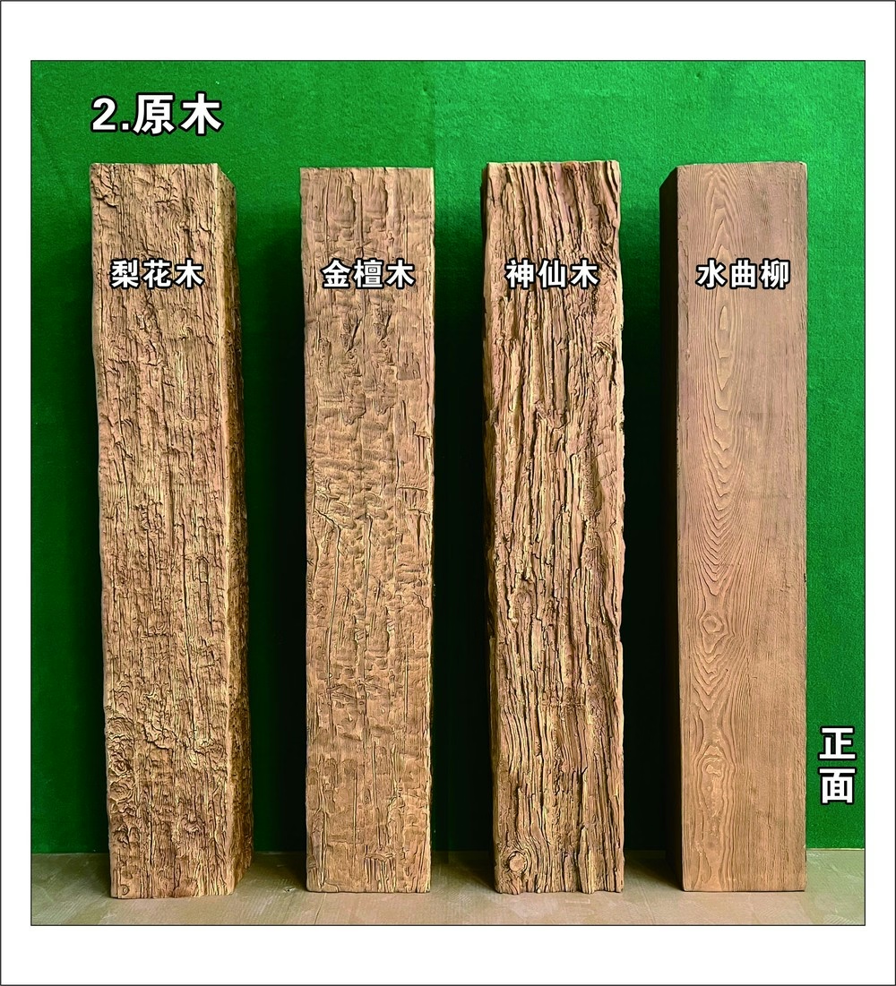
The hotel lobby beam installation looked perfect in December when we completed the project—clean joints, tight alignment, professional execution that satisfied the architect and owner. By June, those same beams showed buckled sections, stressed joints, and visible distortion that prompted angry calls questioning our workmanship. We hadn't anticipated that the 40°F temperature swing between winter installation and summer operations would cause 20-foot polyurethane beams to expand nearly half an inch—enough to buckle sections rigidly attached without expansion accommodation. The expensive repair involved removing and reinstalling beams with proper expansion joints, teaching me that thermal expansion isn't an optional consideration on long spans—it's a fundamental engineering requirement.
All materials expand when heated and contract when cooled. Polyurethane exhibits greater thermal movement than wood or steel, and long spans accumulate dimensional changes that can cause structural problems if installations don't accommodate them. Understanding thermal expansion coefficients, calculating expected movement, and designing installation details that permit this movement prevents failures while maintaining aesthetic quality.
Understanding Thermal Expansion in Polyurethane
The coefficient of thermal expansion (CTE) for rigid polyurethane foam typically ranges from 30-50 × 10⁻⁶ per degree Fahrenheit, depending on specific formulation and density. This means a foot-long piece expands or contracts 0.00003 to 0.00005 inches per degree of temperature change—negligible on short lengths but significant when accumulated across long spans.
The calculation formula for dimensional change is: ΔL = L × CTE × ΔT, where ΔL is length change, L is original length, CTE is the coefficient, and ΔT is temperature change. A 20-foot beam (240 inches) with CTE of 40 × 10⁻⁶ experiencing 60°F temperature swing would change: 240 × 0.00004 × 60 = 0.576 inches—more than half an inch of expansion or contraction that must be accommodated.
Temperature swings in buildings vary significantly by location and building type. Conditioned interior spaces might experience only 10-15°F seasonal variation, while unconditioned spaces can swing 40-60°F or more. Attic installations in hot climates might reach 140°F in summer and 40°F in winter—a 100°F swing causing dramatic dimensional changes. Understanding the temperature range your installation will experience allows accurate movement predictions.
Installation temperature affects the direction of primary movement. Beams installed during winter cold will primarily expand as temperatures rise. Summer installations will contract as temperatures fall. The worst-case scenario involves installing at moderate temperatures where the beam will both expand in summer and contract in winter—requiring accommodation in both directions from the neutral installation position.
Polyurethane exhibits greater thermal expansion than wood, which has CTE around 3-5 × 10⁻⁶ depending on species and grain direction—an order of magnitude less than polyurethane. This difference means installation techniques adequate for timber spans may prove insufficient for polyurethane alternatives. Steel structural beams (CTE ~6-7 × 10⁻⁶) similarly move less than polyurethane, requiring installation approaches specific to the polymer material's properties.
Span Length Thresholds and Risk Assessment
Short beam spans under 8 feet rarely require specific expansion accommodation. The accumulated movement across these lengths—typically under 0.15 inches even in extreme temperature swings—stays within tolerance that standard installation methods handle through adhesive flexibility and material compliance. These short spans can install using continuous adhesive attachment without special provisions.
Medium spans of 8-16 feet enter the transition zone where expansion accommodation may be needed depending on temperature extremes expected. In conditioned interior spaces with minimal temperature variation, standard installation often succeeds. In unconditioned or high-swing environments, these medium spans benefit from expansion joints or flexible attachment strategies preventing stress accumulation.
Long spans exceeding 16 feet require explicit expansion accommodation in most applications. The accumulated movement—potentially exceeding half an inch—will cause problems if ignored. Buckling, joint failures, or adhesive bond failures occur when rigid installations don't permit the dimensional changes that physics demands. Professional installations of long spans must include engineered expansion provisions.
Very long spans over 30 feet—common in commercial lobbies, convention centers, or large residential great rooms—may require multiple expansion joints dividing the span into shorter segments. A 40-foot span might incorporate joints at 10-15 foot intervals, limiting movement between joints to manageable amounts while allowing the total span to expand over an inch without damage.
Expansion Joint Design and Detailing
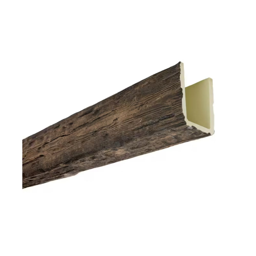
The slip joint represents the simplest expansion accommodation strategy. One beam end attaches rigidly while the opposite end slides within a sleeve or bracket allowing longitudinal movement. The sliding connection must guide movement while preventing visible separation or misalignment. Proper slip joint design maintains appearance through the full range of thermal movement without binding or exposing gaps.
The sleeve detail uses an overlapping beam section at joints—one beam slips inside a slightly larger sleeve section attached to the adjacent beam. As temperature changes, the beams slide within the sleeve connection maintaining coverage without visible separation. The sleeve length must exceed maximum expected movement plus safety margin—typically 1-2 inches minimum sleeve engagement at the most extreme movement position.
Concealed spline joints provide another expansion strategy. A floating spline—a separate piece spanning between beam ends—attaches to neither beam rigidly, allowing both to slide relative to the stationary spline. The spline covers the joint maintaining visual continuity while the beams move independently. This approach works well where visible joint lines are unacceptable but movement accommodation is necessary.
Trim cover plates conceal expansion gaps while allowing movement beneath. Decorative banding or metal straps positioned over expansion joints hide the mechanical function while adding design interest. These covers must attach to only one side of the joint, allowing the other beam to slide beneath as temperatures change. The cover width must exceed maximum gap opening that occurs at extreme contraction positions.
The visual acceptance of visible joints depends on design context. Traditional timber frame aesthetics often include visible joints suggesting authentic construction. These styles accept visible expansion joints as appropriate to the architectural language. Contemporary minimalist designs demanding seamless continuity struggle with visible joints, requiring concealed sleeve or spline strategies even though they complicate installation and cost.
Attachment Strategies Accommodating Movement
Flexible adhesive attachment allows moderate expansion without causing buckling or bond failure. Using adhesive beads rather than continuous coverage—applied in 2-3 inch beads every 12-16 inches—provides intermittent attachment that permits slight beam movement between adhesive locations. The flexibility of construction adhesives allows each bond point to stretch accommodating millimeters of movement without failing.
The mechanical fastener pattern affects movement accommodation significantly. Rigid attachment with screws at close spacing—every 8-12 inches—prevents movement and will cause buckling in long spans. Wider fastener spacing—24-36 inches—with adhesive between provides flexible attachment allowing slight expansion. In very long spans, fasteners might concentrate at one end (the fixed point) with only adhesive at the opposite end (the expansion end).
Slotted fastener holes in beam mounting brackets allow longitudinal sliding while preventing lateral movement or detachment. Mounting blocks attach to ceiling structure, with beams screwing into these blocks through horizontal slots rather than round holes. As temperature changes, the beam slides along the slots—the screws constraining lateral position while allowing longitudinal movement. The slot length must accommodate expected movement plus safety margin.
Floating mounting systems use brackets that themselves can move relative to ceiling structure. These systems—typically used in commercial applications—include mechanical components designed specifically for thermal expansion accommodation. Manufacturers of these specialized systems provide installation instructions and engineering data documenting movement capacity and proper installation procedures.
The attachment pattern must designate a fixed point—typically beam center or one end—where rigid attachment prevents movement in all directions. All other attachment points must allow movement toward or away from this fixed point as temperature dictates. Without a clearly defined fixed point, the beam may "walk" over time as repeated expansion-contraction cycles incrementally shift position.
Installation Environment and Timing Considerations
Installing during moderate temperatures positions beams near the middle of their expansion range, minimizing maximum movement in either direction. Spring and fall installations in seasonal climates allow expansion into summer and contraction into winter both occurring from a neutral starting position. This timing reduces maximum accumulated movement compared to extreme-season installations.
Winter installations in cold climates mean beams will primarily expand as temperatures rise. Expansion joint gaps should be set at their maximum width during cold installation, allowing closure as beams expand without compressive buckling. Summer installations mean beams will contract, requiring joints set at minimum width during warm installation allowing gaps to open as temperatures drop without losing overlap.
Conditioning materials to installation environment temperature before installing helps stabilize dimensions before attachment. Beams delivered to site should acclimate in the installation space for 24-48 hours before installation begins. This acclimation allows material to reach equilibrium with ambient temperature, preventing immediate dimensional change after installation that could stress fresh adhesive bonds before they fully cure.
Adhesive cure time interacts with thermal movement considerations. Beams must remain stationary through initial adhesive cure—typically 24-48 hours—before significant temperature changes occur. Installing before major weather changes that would cause rapid temperature swings risks disturbing uncured adhesive bonds. Weather forecasts should inform installation timing, avoiding periods where temperature swings will occur during critical cure periods.
Special Conditions and Problem Scenarios
Beam-to-beam connections in grid or coffered layouts require expansion provisions at multiple junctions. These perpendicular connections complicate movement accommodation since beams expand in different directions simultaneously. One strategy uses expansion joints only in one beam direction—typically the longer axis—with perpendicular beams attaching flexibly allowing slight position change as the primary beams move.
Curved beams present unique thermal expansion challenges since linear expansion in a curved geometry creates compound movements that are difficult to predict and accommodate. The conservative approach limits curved beam lengths to minimize accumulated expansion, uses flexible attachment allowing slight position adjustment, and accepts that some residual stress will exist. Avoid rigid attachment of long curved beams in environments with significant temperature variation.
Beam penetrations for lighting, HVAC, or other ceiling systems must accommodate beam movement without binding. Lights mounted within beam faces may need oversize mounting holes allowing the beam to slide relative to fixed wiring. Ducts or pipes crossing beams should include flexible connections or clearances preventing interference as beams move. Coordinate these penetrations with thermal movement predictions during design.
Junction between conditioned and unconditioned spaces requires special attention. A beam spanning from air-conditioned interior to unconditioned sunroom or porch experiences temperature gradient along its length—one end hot, the other cool. This differential expansion creates complex stress states and potential bending or twisting. Expansion joints positioned at the thermal boundary—typically where beam crosses the wall separating spaces—accommodate this differential movement.
Monitoring and Maintenance Considerations
Post-installation observation through the first seasonal cycle verifies expansion accommodation performs as designed. Visual inspection at seasonal temperature extremes checks joint positions, looks for buckling or distortion, and verifies that expansion joints open and close as expected. This monitoring catches problems early when correction proves simpler than addressing failures after multiple stress cycles.
Long-term maintenance includes periodic inspection of expansion joints confirming they remain functional. Joints can accumulate debris or paint that interferes with sliding movement. Adhesive in slip joints may gradually seize from dust or environmental contamination. Periodic cleaning and lubrication of moving joints extends system life and prevents binding that would transfer stresses into beam structure.
Documentation of installation details—fixed point locations, expansion joint positions, expected movement ranges—provides valuable information for future maintenance or modifications. When additions or renovations require ceiling work years after original installation, understanding thermal movement provisions prevents inadvertently compromising systems that have functioned properly for years.

Thermal expansion represents a fundamental physical reality that long-span installations must address through engineering rather than ignore hoping problems won't occur. Understanding polyurethane's thermal properties, calculating expected movement for specific conditions, and designing installation details that accommodate dimensional changes prevents failures while maintaining aesthetic quality. The additional complexity thermal expansion adds to installation proves minimal compared to repair costs and client relationships destroyed by failed installations. In long-span applications, expansion accommodation isn't optional refinement—it's mandatory engineering that separates professional results from amateur failures.
Technical References
ASTM standards cited in every specification
Test Data
Lab results from internal testing program
Updated 2026
Reviewed against current product specs