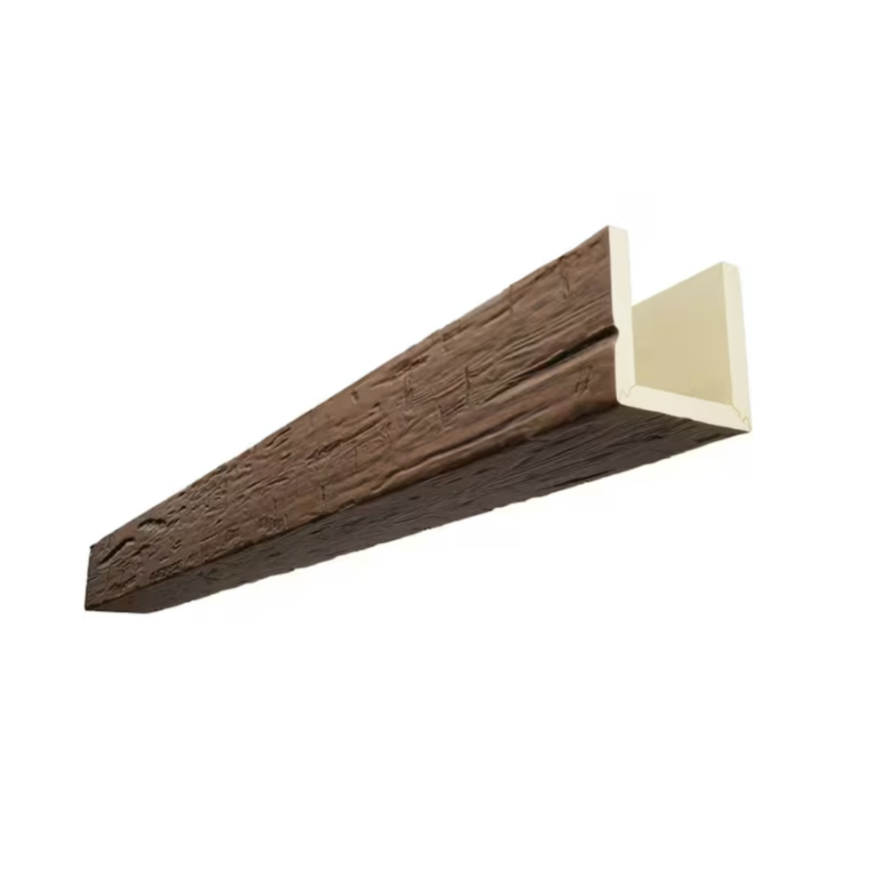
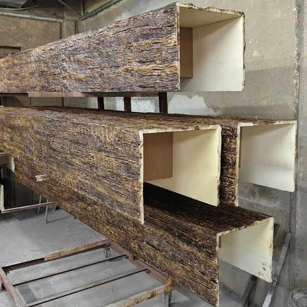
The hotel project specified 4×6 inch beams throughout—a straightforward order until installation began. Beams from the first production batch fit mounting cleats perfectly, sliding onto 3.5×5.5 inch blocking with appropriate clearance. Beams from the second batch, ostensibly identical, barely fit—installers had to force them onto cleats, sometimes splitting beam sides. The third batch fit so loosely that beams visibly shifted on cleats. Investigation revealed U-channel opening variations from 3.625×5.625 inches to 3.875×5.875 inches across batches despite nominal 4×6 external dimensions. Without clear tolerance specifications in our purchase agreement, the manufacturer claimed all variations remained "within normal range." We ended up shimming loose beams and routing oversized openings to achieve consistent fit—adding $12,000 in field labor that proper manufacturing tolerances would have eliminated.
Dimensional tolerance standards defining acceptable variation in U-channel opening sizes prove critical for installations using mounting cleats or structural blocking inside hollow beams. While slight variations might seem inconsequential, cumulative tolerance stack-up between blocking dimensions, beam openings, and required working clearances determines whether installations proceed smoothly or become frustrating exercises in field modification. Understanding appropriate tolerances, measurement methods, and quality control protocols ensures manufacturing consistency while enabling efficient installation.
Understanding Tolerance Fundamentals
Nominal versus actual dimensions distinguish between marketing descriptions and physical reality. A beam described as "4×6 inches" refers to external dimensions that might actually measure 3.875×5.875 inches while U-channel openings might measure 3.5×5.5 inches providing approximately 3/8 inch wall thickness. Clear documentation should specify both external dimensions and internal U-channel openings since installation success depends on internal dimensions.
Tolerance definition establishes acceptable variation from target dimensions—typically expressed as plus/minus values. For example, a 3.5-inch U-channel width might specify ±0.0625 inch tolerance, meaning acceptable dimensions range from 3.4375 to 3.5625 inches. Tighter tolerances cost more to achieve but provide better fit consistency. Appropriate tolerance balances manufacturing cost against installation requirements.
Bilateral tolerances allowing equal variation in both positive and negative directions (±0.0625") suit most applications where either larger or smaller dimensions create equivalent problems. Unilateral tolerances permitting variation in only one direction (+0.000/-0.125") might suit specific applications where oversized or undersized conditions cause different severity problems.
Statistical tolerance concepts including six sigma quality or Cpk capability indices quantify process consistency beyond just specification limits. A process might keep 99.7% of production within ±0.0625" (3 sigma) or 99.9997% within that band (6 sigma). Higher capability requires tighter process control but delivers more predictable results. Understanding statistical concepts helps evaluating manufacturer quality systems.
Tolerance stack-up occurs when multiple dimensional variations combine affecting fit. If beam opening tolerance is ±0.0625", blocking tolerance is ±0.0625", and required clearance is 0.125", worst-case stack-up (beam at minimum opening, blocking at maximum size) leaves only 0.125 - 0.125 = 0 clearance creating interference. Proper tolerance analysis accounts for stack-up preventing specification combinations that create problems.
Industry Standard Tolerances
ASTM and similar standards for polymer products don't specifically address decorative beams but provide general guidance that informed specifications can adapt. ASTM D6662 covering polyurethane architectural millwork suggests ±1/16" (0.0625") for most dimensions, which provides reasonable starting point for beam specifications.
Manufacturer variation reveals that different suppliers maintain different tolerance capabilities ranging from ±1/16" for quality manufacturers to ±1/8" or looser for budget products. Understanding what specific manufacturers actually achieve versus theoretical capabilities prevents specifying tighter tolerances than suppliers can deliver or accepting unnecessarily loose tolerances.
Custom versus standard product tolerances differ—custom beams made specifically for projects might achieve ±0.03125" (1/32") through dedicated tooling while standard catalog products made in high volume might maintain only ±0.0625" (1/16"). Custom tight tolerance costs more but might justify expense for critical applications.
Economic tolerance analysis determines tightest economically achievable tolerances balancing manufacturing cost against value. Reducing tolerances from ±1/16" to ±1/32" might double manufacturing costs while providing minimal installation benefit. Conversely, accepting ±1/8" tolerances to save 10% on material costs might create installation problems costing far more than material savings.

Measurement Methods and Equipment
Caliper measurement using dial calipers or digital calipers provides accurate dimension verification to 0.001-inch resolution. Proper caliper use requires understanding measurement techniques—applying appropriate pressure, measuring at multiple locations, and averaging readings. Calipers prove practical for most installation and quality control applications.
Go/no-go gauges providing simple pass/fail assessment without numerical measurements streamline high-volume inspection. Custom gauges machined to maximum and minimum acceptable dimensions allow rapid checking—if gauge fits, dimension is acceptable; if not, part fails. These specialized tools suit production quality control better than field applications.
Coordinate measuring machines (CMM) offering three-dimensional precision measurement provide comprehensive dimensional verification for complex geometries. CMM inspection proves overkill for routine production but might verify initial tooling or investigate dimensional problems requiring detailed analysis.
Photogrammetry using calibrated cameras and software extracts precise measurements from photographs. This non-contact method suits applications where physical gauge access proves difficult or where comprehensive profiles need mapping. Photogrammetry requires specialized equipment and training but provides capabilities conventional measuring tools can't match.
Statistical sampling strategies determine how many beams to measure and what acceptance criteria apply. Measuring every beam ensures complete verification but proves impractical for large production runs. Statistical quality control following established protocols allows confident quality assessment through manageable sample sizes. Sample plans should reflect production lot sizes and required confidence levels.
Critical Measurement Locations
Opening width and height at beam centers establish primary dimensions affecting mounting fit. Center measurements typically represent narrowest dimensions since molding processes often create slight draft angles that widen openings toward ends. Center dimensions should meet specifications since this is where fit matters most during installation.
End opening dimensions at beam terminations might differ from center dimensions due to manufacturing processes. Some molding creates natural draft—slight taper allowing part release from molds. Understanding whether specifications apply to center dimensions, end dimensions, or both prevents confusion about compliance.
Dimensional variation along length checking measurements at multiple points reveals taper, bow, or inconsistency. Perfectly uniform openings throughout length prove difficult achieving—slight variation is normal and acceptable if within specifications. However, excessive taper makes mounting cleats bind at one end while remaining loose at the other.
Corner radii where U-channel sides meet base affect how square-cornered blocking fits. Sharp internal corners accommodate square blocking precisely while generous radii create gaps at corners that reduce effective bearing area. Corner geometry should coordinate with anticipated blocking or cleat profiles.
Wall thickness at edges affects structural integrity and determines external dimensions relative to internal openings. Consistent wall thickness throughout cross-section indicates quality molding. Variable wall thickness might indicate process problems even if resulting dimensions technically meet specifications.
Fit Classification Systems
Interference fits where beams install tighter than hand-sliding requires force driving beams onto mounting cleats. Interference fits provide maximum security preventing beam movement but require installation effort and risk damaging beams through forcing. Typical interference fits use -0.0625" to -0.125" clearance (blocking 1/16-1/8" larger than beam openings).
Transition fits falling between interference and clearance allow beams sliding onto mounts with modest effort without requiring force or excessive looseness. Transition fits provide security while maintaining practical installation ease. Typical transition fits provide 0.000" to +0.0625" clearance—blocking at or slightly smaller than beam openings.
Clearance fits where beams slide easily onto mounts with visible gap prove easiest to install but might allow excessive movement. Clearance fits suit applications prioritizing installation speed over rigidity or where adhesive provides primary attachment while cleats simply position beams. Typical clearance fits provide +0.0625" to +0.125" clearance.
Fit selection depends on installation methodology, adhesive use, and performance requirements. Adhesive-bonded installations can use looser clearance fits since adhesive prevents movement. Mechanical mounting without adhesive might require tighter transition or interference fits. Understanding how fit affects installation process and final performance guides appropriate specification.
Quality Control Protocols
Incoming inspection at customer facilities verifying received beams meet dimensional specifications catches problems before installation begins. Measuring representative samples from each delivery lot provides quality confirmation or reveals nonconformance requiring resolution before proceeding. This receiving inspection proves particularly important for large projects where dimensional problems could create expensive installation delays.
First article inspection during production runs checks initial beams from new mold setups before full production begins. If first articles meet specifications, production proceeds confidently. If not, adjustments occur before substantial nonconforming production accumulates. First article inspection prevents problems rather than just detecting them.
In-process monitoring during production runs catches progressive dimensional drift before it produces out-of-specification parts. Statistical process control charts plotting measurements over time reveal trends requiring intervention. This real-time monitoring prevents problems rather than discovering them through final inspection.
Final inspection before shipment provides last quality verification ensuring only conforming products reach customers. Whether inspecting 100% of production or statistical samples, final inspection creates quality gate preventing knowingly shipping nonconforming material.
Documentation systems recording measurements, inspection results, and any nonconformance creates quality records supporting continuous improvement while providing traceability if problems develop. Digital inspection records linked to lot numbers enable investigating which specific production runs any field problems originated from.
Nonconformance Management
Acceptance criteria defining when dimensional variations require rejection versus when they remain acceptable despite non-ideal measurements balances perfectionism against practicality. Specifications define ideal targets but judgment determines whether minor variations truly create problems or just offend perfectionist sensibilities without affecting function.
Rework options for slightly nonconforming beams might include light sanding or routing to bring dimensions into specification. Rework proves economical when deviation is minor but becomes impractical for severe nonconformance. Determining rework feasibility and cost-effectiveness guides accept/reject/rework decisions.
Use-as-is decisions accepting nonconforming material for specific applications where dimensional variations prove inconsequential allows recovering value from otherwise waste. Beams with oversized openings might suit applications using adhesive-only mounting without cleats. Use-as-is requires informed analysis ensuring actual applications tolerate variations.
Return and replacement for material failing specifications and unsuitable for intended applications protects buyers from unusable products. Clear purchase agreements specifying tolerance requirements and remedies for nonconformance prevent disputes about whether material meets contractual obligations.
Root cause analysis investigating why nonconformance occurred prevents recurrence. If tooling wear caused dimensional drift, preventive maintenance prevents repeat problems. If material formulation changed, reverting to proven specifications restores quality. Effective nonconformance management looks beyond symptoms to underlying causes.
Installation Adaptation Strategies
Blocking customization by cutting or planning mounting cleats to actual received beam dimensions accommodates dimensional variation without rejecting beams. While adding installation labor, custom-fit blocking allows using beams despite dimensional inconsistency. This pragmatic approach suits situations where returning material creates unacceptable delays.
Shim installation filling gaps between loose-fitting beams and mounting cleats prevents movement and rattling. Small wood shims or construction adhesive fill gaps creating snug fit from initially loose assemblies. While adding labor, shimming proves faster than waiting for replacement material.
Opening modification using routing or sanding to enlarge tight beam openings allows fitting beams onto oversized blocking. This field correction requires care avoiding visible damage to beam exteriors but proves practical for moderately tight fits. Severe interference makes routing impractical.
Adhesive gap-filling using generous adhesive application in loose-fitting assemblies bonds beams securely despite excessive clearance. Modern gap-filling adhesives bond effectively across substantial gaps when simple clearance-fit adhesives might fail. This approach accepts dimensional variation while maintaining secure installation.
Economic Impact Analysis
Rejection costs including wasted material, shipping, handling, and project delays from nonconforming dimensional quality motivate adequate tolerance control. If 10% of $20,000 material order fails inspection, rejection costs exceed $2,000 plus project delays potentially costing multiples of material value. These costs justify manufacturing investment in dimensional control.
Field correction labor when installers modify either beams or blocking achieving proper fit typically costs $5-15 per beam. Across hundreds of beams, field correction costs exceed potential savings from accepting looser manufacturing tolerances. Labor costs generally dwarf material costs making factory precision economical despite higher unit costs.
Schedule impacts when dimensional problems delay installations waiting for replacement material or while installers struggle with difficult fits create opportunity costs beyond direct expense. Project delays disappoint customers, potentially trigger late-completion penalties, and prevent crews moving to next projects. These hidden costs multiply direct correction expenses.
Professional Standards and Expectations
U-channel dimensional tolerance standards establish manufacturing quality expectations ensuring hollow beams fit mounting systems reliably. While perfect dimensional consistency proves impossible, maintaining reasonable tolerances—typically ±1/16 inch for quality products—enables smooth installation while remaining economically achievable. Understanding tolerance specifications, measurement methods, and quality control protocols allows manufacturers producing consistent products, contractors specifying appropriate standards, and installers confidently expecting material that installs without extensive field correction.
For professionals throughout the beam supply chain—manufacturers, distributors, contractors, and installers—dimensional tolerance awareness separates quality-focused operations from those accepting whatever variation occurs and dealing with consequences during installation. The investment in proper dimensional control proves minor compared to costs of field problems that loose tolerances create.
Technical References
ASTM standards cited in every specification
Test Data
Lab results from internal testing program
Updated 2026
Reviewed against current product specs