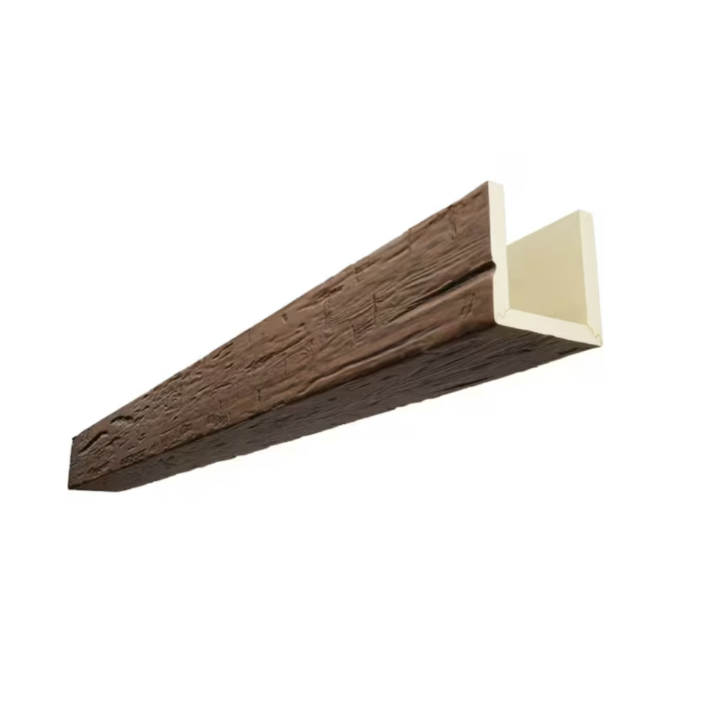
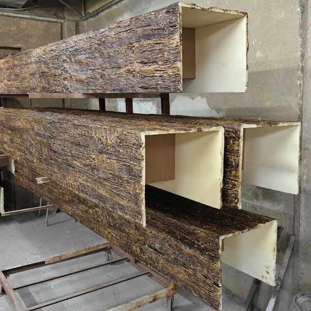
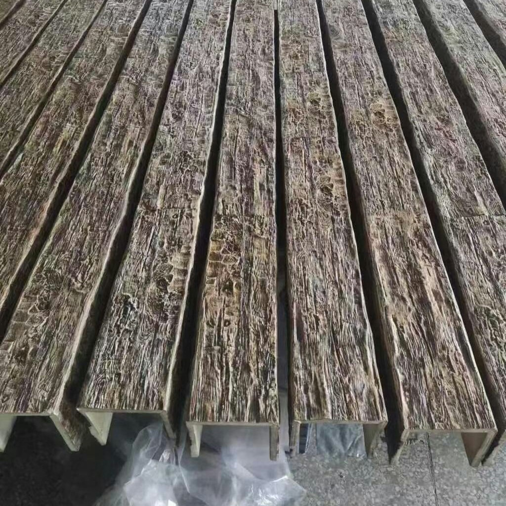
The conference center featured dramatic 24-foot clear spans across the main hall—perfect for showcasing impressive exposed beams. We specified hollow polyurethane beams mounted with adhesive and fasteners at 4-foot intervals following our standard residential installation protocol. Two weeks after installation, facilities management reported visible beam sagging at mid-spans between mounting points. Inspection revealed 1.5-inch deflection at centers of 4-foot unsupported sections—the 3-pound-per-foot beam weight created cantilever loads exceeding what simple end-fastening could support. We remediated by installing concealed intermediate support brackets every 2 feet, adding internal aluminum channel reinforcement, and increasing adhesive coverage. That $8,000 remediation taught me that long-span installations demand structural analysis rather than applying residential best practices to commercial scale applications.
Weight distribution analysis for long-span beam installations requires understanding structural mechanics, calculating deflection under self-weight, and designing support systems preventing sagging that undermines appearance despite adequate safety margins. While polyurethane beams weigh far less than solid wood equivalents, their length and flexibility demand appropriate support preventing visible deflection that makes installations appear amateur despite technically adequate strength.
Understanding Structural Mechanics Fundamentals
Self-weight loading creates distributed loads along beam lengths that mounting systems must support. Unlike concentrated loads at specific points, distributed self-weight creates bending moments proportional to span squared—doubling span quadruples maximum bending moment. This relationship explains why support spacing proves critical for longer beams.
Cantilever action occurs between support points where beam sections span unsupported. Each section between fasteners acts as a simply-supported beam experiencing maximum deflection at mid-span. Deflection varies with fourth power of span—doubling distance between supports increases deflection sixteen-fold. This dramatic relationship demands close support spacing for long installations.
Material stiffness quantified through elastic modulus determines resistance to bending. Polyurethane elastic modulus typically ranges from 100,000-300,000 psi—far lower than wood (1-2 million psi) or steel (29 million psi). Lower stiffness means polyurethane beams deflect more than wood beams under equivalent loads, requiring closer support spacing despite lighter weight.
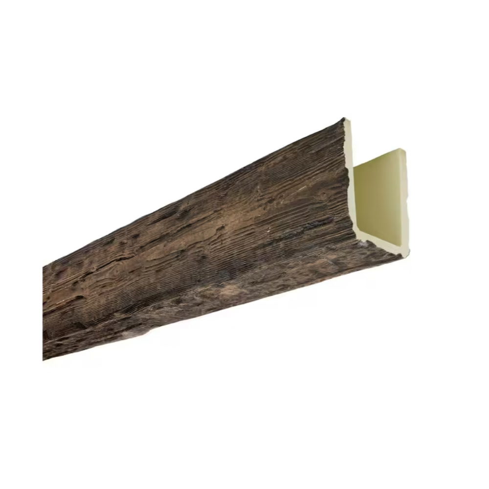
Section properties including moment of inertia (I) and section modulus (S) determine bending resistance. Hollow U-channel beams have lower section properties than solid profiles—a 4×6 inch hollow beam might have moment of inertia of 8-12 in⁴ versus 72 in⁴ for solid section. Reduced stiffness from hollow profiles demands appropriate support.
Deflection limits for visual acceptability typically restrict deflection to span/180 or approximately 0.67 inches per 10 feet. Structural codes might allow greater deflections before failure, but visible sagging creates unacceptable appearance well before structural concern. Aesthetic deflection limits govern decorative installations more than strength requirements.
Calculating Beam Properties and Loads
Weight determination using manufacturer specifications or direct measurement establishes loads mounting systems must support. Typical hollow polyurethane beams weigh 1.5-4 pounds per linear foot depending on size and wall thickness. An 8×8 inch beam might weigh 3.5 lb/ft while 4×4 inch beam weighs 1.8 lb/ft. Accurate weight data proves essential for deflection calculations.
Span length measurement between support points defines structural spans requiring analysis. Support spacing of 48 inches creates very different demands than 24-inch spacing despite identical total beam length. Each unsupported section requires individual analysis—varying support spacing creates varying structural demands.
Section geometry measurement or specification determines moment of inertia (I) used in deflection calculations. For rectangular hollow sections, I = (outer width × outer height³ - inner width × inner height³) / 12. Manufacturers should provide section properties though calculating from dimensions provides verification.
Material properties including elastic modulus (E) and allowable stress affect structural capacity. Polyurethane E typically ranges from 100,000-300,000 psi—higher values indicate stiffer materials deflecting less. Manufacturers should specify E values though generic values provide reasonable estimates absent specific data.

Deflection Calculation Methods
Simple beam formula for uniformly distributed loads provides basic deflection estimates. Maximum deflection = (5 × w × L⁴) / (384 × E × I), where w = distributed load (lb/in), L = span (inches), E = elastic modulus (psi), I = moment of inertia (in⁴). This formula assumes simple support at ends—actual installations with adhesive and fasteners approximate this condition.
Worked example: 4×6 inch hollow beam (I = 10 in⁴, E = 200,000 psi, w = 2.5 lb/ft = 0.208 lb/in) spanning 48 inches between supports: Deflection = (5 × 0.208 × 48⁴) / (384 × 200,000 × 10) = 0.135 inches. This deflection (span/356) appears acceptable. Same beam spanning 60 inches: Deflection = 0.332 inches (span/181)—borderline acceptable. At 72 inches: Deflection = 0.688 inches (span/105)—unacceptable sagging.
Software tools including engineering calculation programs or online beam calculators streamline analysis while reducing calculation errors. Free engineering calculators available online handle simple beam deflection calculations inputting load, span, material properties, and section properties. These tools prove valuable for quick analysis though understanding calculation fundamentals remains important.
Conservative assumptions using lower-bound material properties and upper-bound loads provides safety margins. If material E ranges 150,000-250,000 psi, using 150,000 provides conservative deflection estimates. Similarly, using maximum specified weight rather than typical provides margin. Conservative analysis prevents underestimating deflection risks.
Testing and validation through trial installations or test specimens allows empirical deflection measurement verifying calculations. Measuring actual deflection of representative beam sections under self-weight confirms whether analytical predictions match reality. Empirical validation proves particularly valuable when material properties remain uncertain.
Support Spacing Determination
Target deflection limits establishing maximum acceptable deflection guides support spacing. If limiting deflection to span/240 (0.5 inches per 10 feet), this deflection limit combined with beam properties determines maximum support spacing. Working backward from deflection limits to allowable spans provides design guidance.
Spacing charts creating tables showing maximum support spacing for various beam sizes, weights, and deflection criteria streamlines design. Example chart might show 4×6 beams require 36-inch spacing for span/240 deflection limit while 6×8 beams allow 48-inch spacing. These charts enable rapid design decisions without repeated calculations.
Practical constraints including ceiling joist spacing, blocking locations, or aesthetic considerations might prevent optimal spacing. If structural analysis indicates 30-inch spacing but joists space 24 inches, attaching at every other joist (48 inches) requires determining whether double spacing proves acceptable or demands reinforcement. Balancing structural ideals with practical constraints requires judgment.
Safety factors providing margin beyond calculated minimums account for uncertainties in material properties, installation quality, and future conditions. Using 50% safety factor—designing for 1.5x calculated deflection—provides reasonable margin. Designing to span/180 when targeting span/240 incorporates this safety thinking.
Support System Design
Adhesive attachment providing distributed bonding along beam lengths offers superior deflection control compared to discrete mechanical fasteners. Continuous adhesive bead creates nearly uniform support preventing localized deflection between fasteners. However, adhesive-only support requires adequate bond strength and proper surface preparation ensuring reliable long-term attachment.
Mechanical fastening using screws or nails at regular intervals provides positive attachment but creates discrete support points. Beams span between fasteners creating small cantilever deflections. Closer fastener spacing reduces these deflections—perhaps 12-16 inch fastener spacing for long spans versus 24-36 inches for shorter installations.
Combined systems using both adhesive and mechanical fasteners leverage advantages of each—adhesive provides distributed support while fasteners ensure positive attachment. This belt-and-suspenders approach provides superior deflection control and redundant load paths. Most professional installations use combined attachment for long-span applications.
Continuous blocking running full beam lengths and securely attached to ceiling framing provides ideal support preventing deflection. This approach requires substantial blocking material and installation labor but delivers best deflection control. Continuous blocking suits high-end installations where appearance criticality justifies extra effort and cost.
Intermediate hangers using concealed support brackets at mid-span between end attachments control deflection without continuous blocking. These discrete intermediate supports reduce effective spans without blocking running entire lengths. Hangers prove particularly valuable for retrofit installations where continuous blocking installation proves impractical.
Reinforcement Strategies
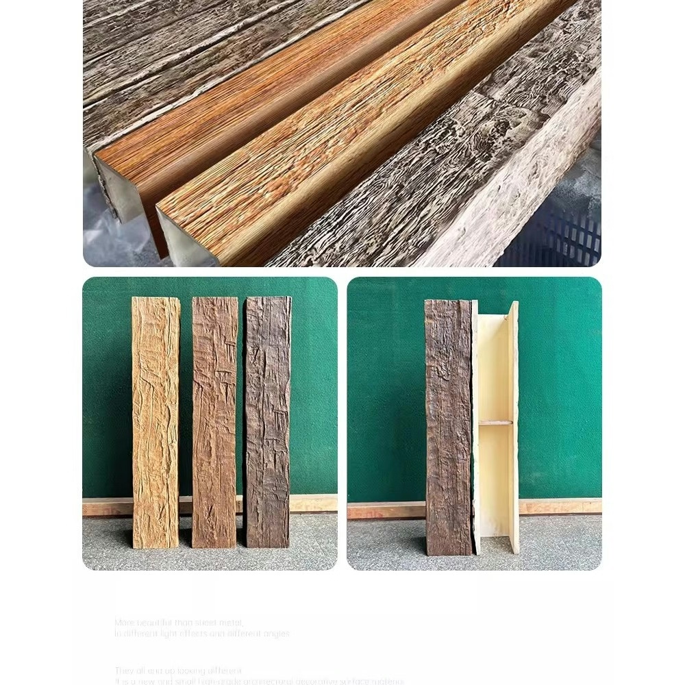
Internal reinforcement using aluminum channels, steel angles, or wood inserts within hollow beam U-channels dramatically increases stiffness while remaining concealed. A 1×2 inch aluminum channel running beam length might increase section modulus 3-5x, allowing much longer unsupported spans. Internal reinforcement provides structural improvement without affecting appearance.
External stiffeners using decorative strapping, bands, or corbels can provide support while appearing intentional design elements rather than structural necessities. Decorative iron bands at intervals along beams add both visual interest and structural support. This approach embraces support requirements as design opportunities.
Composite construction bonding stiffening materials to beam exteriors creates composite sections with improved properties. Bonding thin plywood or aluminum sheets to beam tops creates I-beam effect where stiffer material placed away from neutral axis dramatically improves stiffness. However, exterior reinforcement affects appearance, limiting this approach to concealed surfaces.
Reduced span alternatives reconsidering designs to eliminate long unsupported spans through additional beams, columns, or design modifications might prove simpler than reinforcing existing designs. Sometimes structural challenges indicate design reconsideration rather than engineering around problems.
Installation Technique Considerations
Temporary support during adhesive cure prevents deflection during installation before adhesive reaches full strength. Using adjustable supports, struts, or temporary bracing holds beams straight while adhesive cures over 24-48 hours. Temporary support proves particularly important for long spans where self-weight could cause adhesive squeeze-out or slumping before cure.
Pre-cambering installing beams with slight upward curve compensates for anticipated deflection under self-weight. When loaded, pre-cambered beams deflect to straight rather than sagging. However, calculating appropriate pre-camber and achieving it during installation requires expertise. This advanced technique suits critical applications where appearance demands perfection.
Stress-free installation ensuring beams install without bending, twisting, or forcing prevents residual stresses that might cause long-term deflection or damage. If beams must force into position during installation, they'll relax over time potentially creating gaps or deflection. Stress-free installation requires accurate layout and proper preparation.
Adhesive selection using appropriate adhesive types and quantities ensures adequate bond strength supporting beam weight. Some adhesives cure to rigid bonds while others maintain flexibility—rigid adhesives provide better immediate strength while flexible adhesives accommodate thermal movement. Selecting adhesives appropriate for structural application versus just aesthetic bonding matters.
Long-Term Deflection Considerations
Creep and relaxation in polymers causes progressive deflection over time under sustained loads. Polyurethane exhibits some creep though less than many plastics. Long-term deflection might reach 1.5-2x initial deflection over years. Designing for long-term performance requires accounting for creep, using higher safety factors, or accepting that installations might require adjustment after years of service.
Temperature effects on material properties include softening at elevated temperatures reducing stiffness. Polyurethane elastic modulus decreases with temperature—perhaps 20-30% reduction from 70°F to 100°F. Ceiling temperatures in hot climates or below uninsulated roofs might reach levels affecting deflection. Temperature considerations prove particularly important for high-exposure applications.
Adhesive aging affecting bond strength over decades creates support degradation even if beams remain structurally sound. Adhesive bonds might weaken over 15-20 years from various aging mechanisms. Periodic inspection and potential adhesive renewal might prove necessary for permanent installations. Understanding adhesive limitations prevents assuming eternal bonding.
Field Assessment and Correction
Deflection measurement using laser levels, string lines, or straightedges quantifies existing deflection determining whether correction proves necessary. Measuring from level reference to beam bottom at multiple points reveals deflection patterns. Deflections under span/240 (0.5 inches per 10 feet) generally appear acceptable while greater deflections warrant correction.
Correction methods for excessive deflection include adding intermediate supports, installing reinforcement, or adjusting mounting systems. Often, adding 2-3 intermediate support points along problem spans eliminates visible deflection without complete reinstallation. Concealed bracket supports prove particularly effective for correction without disrupting finishes.
Preventive measures during new installations including appropriate support spacing, reinforcement, and installation techniques prevent deflection problems rather than correcting them after occurrence. Planning support systems during design proves far easier than remediating installed beams showing deflection.
Documentation and Verification
Engineering calculations documenting deflection analysis, support spacing determinations, and safety factors creates records supporting installation decisions. If deflection problems develop later, documentation proves that installations followed rational design processes. Absent documentation, installers might face liability for installations that weren't actually designed inadequately.
Load testing under controlled conditions verifying that installations meet deflection requirements provides empirical validation. Testing might involve temporary additional loading or simply measuring deflection under self-weight comparing to predictions. Testing proves particularly valuable for unusual configurations where analytical predictions carry uncertainty.
Inspection protocols including initial post-installation inspection plus periodic monitoring document long-term performance. Initial inspection establishes baseline deflection while periodic checks reveal whether progressive deflection occurs indicating creep or adhesive degradation. Proactive monitoring enables early intervention preventing minor issues becoming major problems.
Code and Liability Considerations
Structural requirements for decorative elements often fall into gray areas—purely decorative elements might not trigger structural code review while elements with any support function face requirements. Understanding whether local authorities consider decorative beams as structural or non-structural affects approval processes and liability exposure.
Professional liability for design and installation failures creating property damage or injury motivates appropriate structural analysis. While polyurethane beam failures rarely threaten life safety, falling beams can cause property damage and potential injury. Professional practice demands appropriate due diligence proportional to risks.
Professional Engineering Excellence
Weight distribution analysis for long-span unsupported beam sections requires understanding structural mechanics, calculating deflection under self-weight, and designing support systems preventing visible sagging. While polyurethane beams weigh far less than wood alternatives, their length and flexibility demand appropriate support spacing, potential reinforcement, and proper installation technique. For contractors installing beams in commercial spaces with dramatic spans, systematic structural analysis separates professional installations from amateur work that might appear adequate initially but develops obvious problems over time.
The discipline to perform these calculations, incorporate adequate support, and verify performance through inspection distinguishes professional practice from casual installation approaches that assume lightweight materials need minimal support. Structural thinking applied to decorative elements prevents problems while maintaining appearance that makes installations successful.
Technical References
ASTM standards cited in every specification
Test Data
Lab results from internal testing program
Updated 2026
Reviewed against current product specs