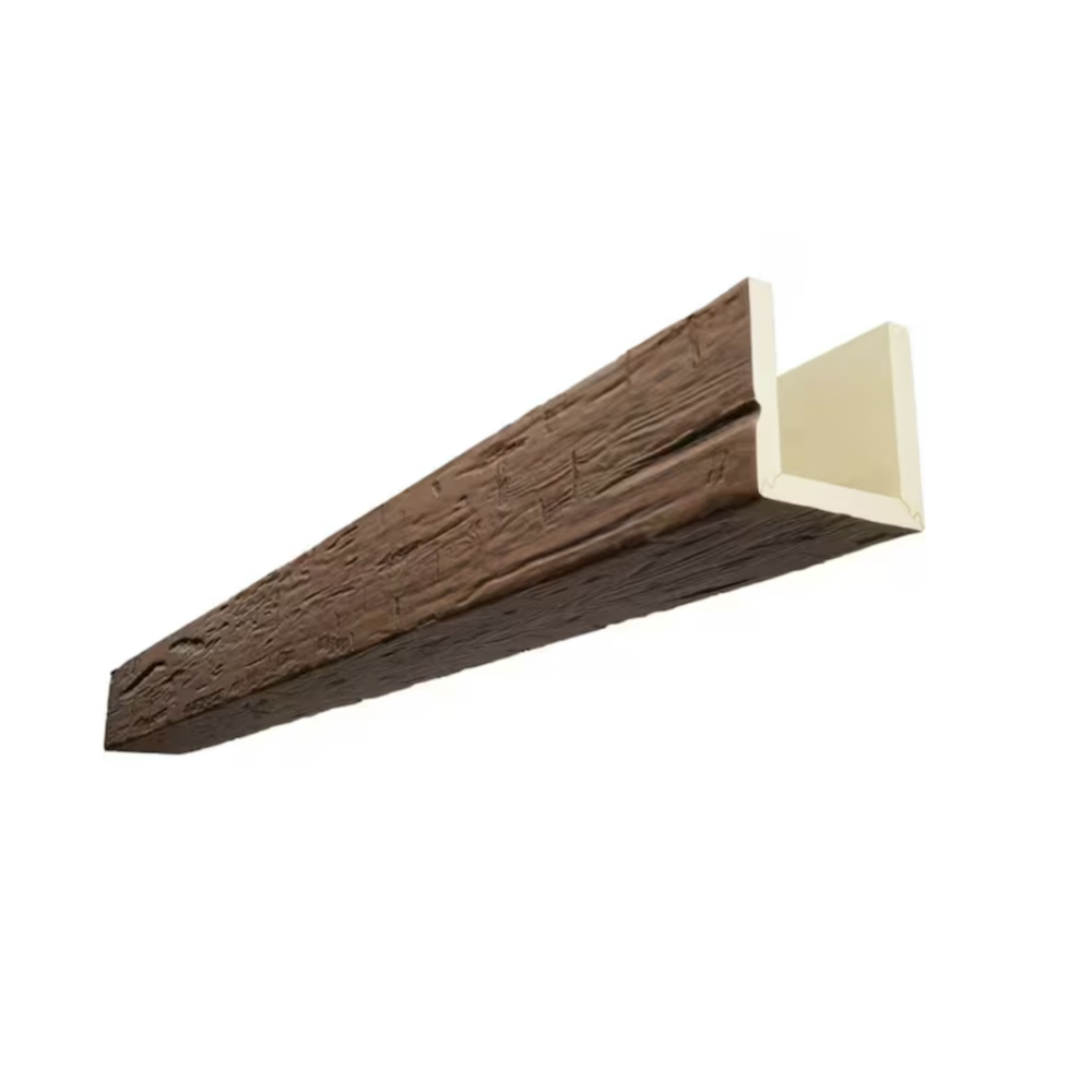
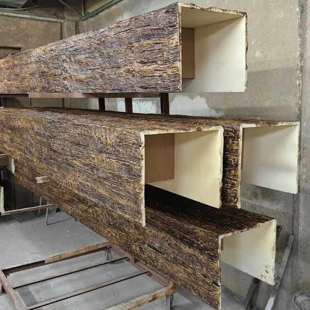
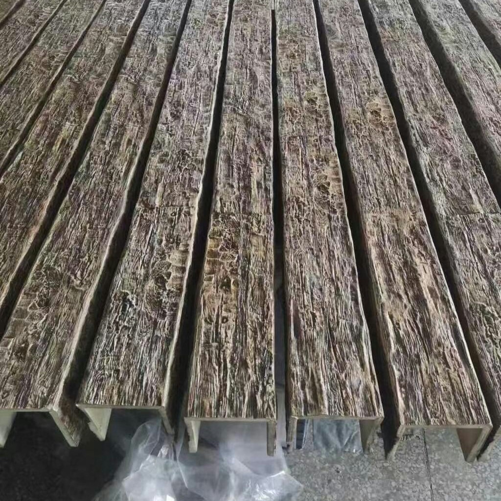
The restaurant renovation featured dramatic exposed beams across the dining room ceiling—beautiful design creating immediate ambiance. However, the architect's lighting plan required 24 recessed fixtures, 6 pendant drops, and 3 ceiling fans integrated throughout the beamed ceiling. The general contractor called asking how to route electrical without visible conduit crossing beam exteriors or cutting through beams compromising their appearance. The original design lacked electrical routing strategy—nobody had considered how wiring would reach fixtures in the beam-intensive ceiling. We coordinated routing options: chasing wires within hollow beam channels where paths allowed, creating concealed conduit runs above blocking between joists, and strategically positioning junction boxes at beam intersections allowing transitions between routing methods. That coordination added $8,000 and three weeks to the schedule—planning that should have occurred during design preventing reactive problem-solving during construction.
Wire chasing and electrical integration in beam-heavy ceiling designs requires coordinating structural, architectural, and electrical systems preventing conflicts while maintaining code compliance and aesthetic intent. Understanding electrical code requirements, routing strategies, and installation sequencing allows successful integration without compromising safety or appearance. Planning electrical paths during design proves far easier than solving routing problems during installation when flexibility vanishes.
Understanding Electrical Code Requirements
NEC (National Electrical Code) compliance governs all electrical installations including routing methods, junction box accessibility, and wiring protection. Local amendments might impose additional requirements beyond NEC minimums. Understanding applicable codes prevents installations requiring expensive rework when inspections reveal violations.
Wiring method requirements specify acceptable cable types and protection for various conditions. Non-metallic cable (Romex) requires protection from physical damage—exposed cables crossing or mounted to surfaces need protection. Armored cable (MC) or conduit provides physical protection but costs more and proves less flexible. Understanding when each method applies guides appropriate material selection.
Junction box accessibility mandates that all junction boxes remain accessible without removing permanent building elements. Boxes concealed within sealed ceiling assemblies or behind decorative beams without removable access panels violate code. Planning junction box locations where access remains possible proves essential for code compliance.
Conductor ampacity and derating requirements limit current-carrying capacity based on conductor size, insulation type, ambient temperature, and bundling. Multiple conductors in confined spaces—perhaps routing several circuits through hollow beams—require derating calculations ensuring conductors don't overheat. Proper ampacity calculations prevent fire hazards and code violations.
Grounding and bonding requirements ensuring electrical safety through proper equipment grounding and system bonding apply regardless of decorative treatments concealing electrical work. Metal junction boxes, light fixtures, and equipment must properly ground. Cutting corners on grounding to simplify installation creates serious safety hazards.
Planning Electrical Routes During Design
Lighting layout coordination between architectural beam placement and electrical fixture locations should occur during design development preventing conflicts. If beams run parallel every 4 feet but lighting requires 6-foot grid, establishing compatible spacing prevents installation conflicts. Early coordination allows adjusting either beam or lighting layouts achieving compatible geometry.
Circuit planning determining how many circuits required, where panels locate, and how circuits distribute throughout spaces affects routing complexity. Consolidating circuits reduces wire runs while excessive circuit subdivision increases routing challenges. Balancing electrical efficiency against routing practicality requires coordinated planning.
Junction box strategy establishing where junction boxes locate, how circuits transition between routing methods, and how accessibility maintains creates routing framework. Strategic junction box placement at beam intersections, hidden above blocking, or within accessible ceiling areas enables wire routing flexibility while maintaining code compliance.
Collaboration timing between architects, lighting designers, and electrical engineers during design development rather than during construction enables integrated solutions. Value engineering or coordination meetings specifically addressing electrical-architectural integration reveal potential conflicts when solutions remain flexible versus discovering problems when construction commitments prevent elegant resolution.


Routing Through Hollow Beam Channels
U-channel access in hollow decorative beams provides convenient wire routing paths when beam orientations align with required electrical paths. Wires entering beam channels at one end can run lengths emerging at opposite ends or through strategic openings along lengths. This concealed routing eliminates visible conduit while providing physical protection.
Entry and exit point planning determines where wires enter/exit beam channels reaching junction boxes or fixtures. Drilling blocking or ceiling panels allows wires transitioning between ceiling cavities and beam interiors. Entry/exit locations should align with junction boxes or fixture locations minimizing exposed wiring requiring protection.
Wire capacity limits within beam channels prevent overfilling channels with excessive conductors. NEC fill requirements limiting conductor area to 40% of raceway area apply to beam channels used as raceways. Overfilled channels create heat buildup and installation difficulty pulling wires. Calculating fill capacity prevents overloading channels.
Fire-stopping requirements at penetrations where wires exit beam channels into ceiling cavities or building assemblies require approved fire-stop materials maintaining fire ratings. Simply drilling holes without fire-stopping compromises fire-rated assemblies violating code. Proper fire-stopping maintains building safety while allowing electrical penetrations.
Support and securing requirements mandate supporting cables at specified intervals—typically 4.5 feet for non-metallic cable. Cables running through beam channels require securing at ends and at intervals along runs. Cable ties, staples, or clips maintain proper support preventing cable sagging or shifting.
Blocking and Framing Integration
Concealed routing above blocking where mounting cleats attach to ceiling framing creates wire paths between joists above beam assemblies. This above-blocking routing keeps wires completely concealed while remaining accessible during installation. Coordinating blocking placement with joist spacing facilitates this routing strategy.
Perpendicular joist crossing where wire paths must cross perpendicular to joist direction requires drilling joists or routing through joist bays. Joist drilling must follow code restrictions—holes in middle third of span, maximum 1/3 joist depth, minimum 2 inches from edges. Improper joist drilling compromises structural integrity requiring expensive repairs.
Soffit utilization in areas where dropped soffits or ceiling height transitions exist provides generous wire routing space. Soffits often contain substantial void space ideal for electrical routing. Coordinating beam and soffit locations allows soffits concealing electrical complexity while beams create visual interest in simpler ceiling areas.
Attic access strategies for spaces with accessible attics above allow routing wires through attic spaces above insulation, dropping down through ceilings at fixture and junction box locations. Attic routing provides maximum flexibility though requires proper insulation contact ratings for recessed fixtures and maintaining insulation effectiveness around penetrations.
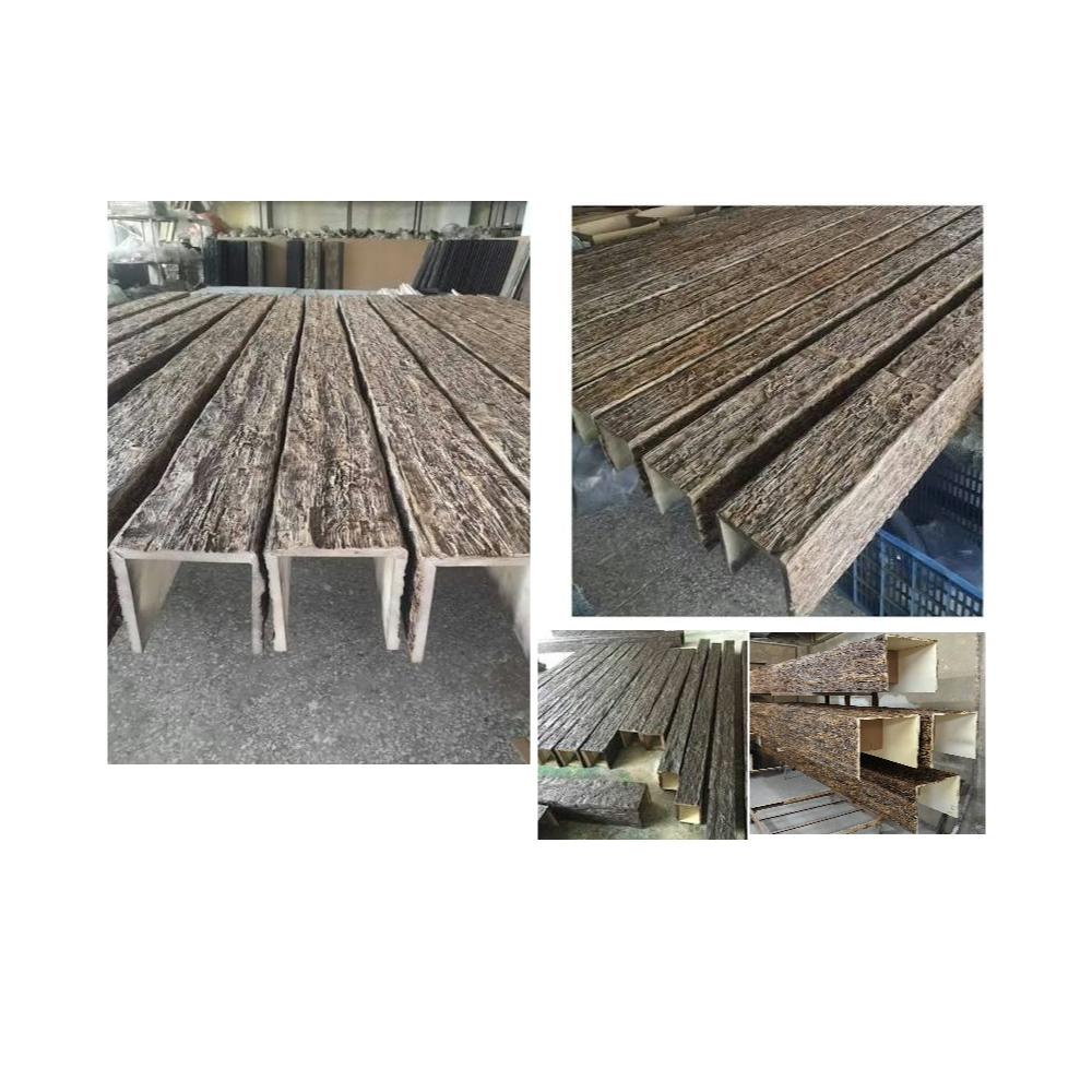
Junction Box Placement Strategies
Beam intersection locations where beams cross or terminate provide natural junction box opportunities. Mounting junction boxes at these intersections allows boxes remaining concealed by beam configurations while remaining technically accessible. Custom fabricated or modified beam sections might include removable panels providing access.
Above-blocking locations mounting junction boxes on ceiling surfaces above decorative beam blocking but below ceiling finish provides accessibility through beam removal. While decorative beams might mount permanently, if removable without damaging ceiling finishes, code allows junction boxes above blocking accessed through beam removal.
Accessible ceiling areas in spaces with removable ceiling tiles or access panels allow junction box placement in accessible ceiling zones. Wire routing then transitions from accessible areas through beam channels or concealed paths to final destinations. This strategy suits commercial applications with accessible ceiling systems.
Fixture locations integrating junction boxes directly at light fixture mounting points eliminates separate junction box requirements. Fixture-rated boxes support fixture weights while providing wire termination. This direct mounting approach simplifies systems when fixture locations align with routing possibilities.
Remote accessible locations placing junction boxes in nearby accessible spaces—closets, utility rooms, attic accesses—with wire runs extending to beam areas maintains accessibility while separating junction points from decorative spaces. Extended home runs increase wire costs but solve accessibility challenges.
Managing Multiple Circuits
Color coding and labeling using consistent identification schemes for multiple circuits prevents confusion during installation and future service. Labeling wires at junction boxes and panel connections enables tracing circuits. Circuit directories at panels should document circuit purposes and approximate routing for troubleshooting.
Bundling considerations when multiple circuits route together require derating calculations and physical organization preventing tangled wire masses. Grouping circuits running similar paths simplifies routing but requires proper derating. Cable ties or bundling straps maintain organization during installation.
Circuit separation requirements including physical spacing between incompatible circuit types—line voltage versus low voltage, different voltage systems—prevents interference and maintains safety. Understanding separation requirements guides whether circuits can share routing paths or require independent routes.
Dedicated neutral requirements for modern circuits and multi-wire branch circuits demand careful planning and wire management. Shared neutral circuits require specific wiring configurations and proper identification. Modern code requires neutral conductors for all switch locations creating wire quantity increases versus older wiring practices.
Pendant and Chandelier Integration
Support requirements for heavy fixtures require structural support independent of electrical boxes. Ceiling fan/fixture-rated boxes support up to 70 pounds; heavier fixtures need supplementary structural support. Planning structural support for substantial chandeliers during beam blocking installation prevents retrofit challenges.
Canopy coordination where fixture canopies conceal junction boxes and wire connections requires appropriately sized and located boxes aligned with canopy dimensions. Oversized boxes might not conceal under canopies while undersized boxes prevent proper wire termination. Verifying canopy dimensions during rough-in prevents fit problems.
Adjustable height fixtures using aircraft cable or chain suspension require ceiling attachment points and sufficient wire length accommodating adjustment. Planning wire slack and support hardware during rough-in enables field-adjustable fixture heights. Inadequate wire length prevents height adjustment while excessive creates concealment challenges.
Ceiling Fan Installation
Structural support for ceiling fans requires fan-rated boxes and blocking supporting fan dynamic loads. Standard junction boxes don't provide adequate support—only fan-rated boxes approved for fan loads should support fans. Installing proper boxes during rough-in proves far easier than retrofitting.
Balance and vibration considerations require fans mounting to solid blocking or structural framing. Fans attached only to drywall or inadequate blocking create vibration transmitting through ceiling structures. Proper mounting prevents annoying vibration and potential long-term damage.
Downrod length planning for vaulted or high ceilings requires coordinating electrical wire length with expected downrod extensions. Insufficient wire length prevents using long downrods while excessive creates concealment challenges. Planning wire length based on expected ceiling heights and downrod requirements prevents problems.
Low-Voltage Integration
LED driver and transformer placement for low-voltage lighting requires accessible locations for these components. Drivers typically mount remotely from fixtures requiring wire runs between drivers and lights. Planning driver locations—perhaps above blocking or in accessible ceiling areas—enables maintenance while concealing equipment.
Control wiring for dimming, switching, and smart lighting systems adds complexity beyond simple power wiring. Control wires might route separately from power requiring additional wire paths. Understanding control system requirements early enables planning appropriate routing.
Data and communication wiring for smart home systems, speakers, or other low-voltage systems often routes alongside power wiring requiring separation maintaining signal quality. Understanding separation requirements prevents interference while allowing shared routing where appropriate.
Troubleshooting and Service Access
Future service access planning for inevitable maintenance, repair, or modification requires thinking beyond initial installation to long-term serviceability. If wire paths prove so concealed and convoluted that service requires extensive demolition, systems prove practically unrepairable. Balancing concealment against service access creates sustainable installations.
Documentation through as-built drawings, photographs, and written descriptions creates records enabling future service. Documenting wire routing, junction box locations, and circuit assignments helps future electricians understanding systems without exploratory demolition. Digital photos during rough-in provide valuable future references.
Testing and verification before concealing work through insulation testing, continuity checks, and trial energization catches problems while correction remains simple. Testing after concealment makes problems exponentially harder diagnosing and correcting. Comprehensive rough-in testing proves time well spent.
Coordination with Other Trades
Insulation contractors must understand electrical routing avoiding compression or damage during insulation installation. Compressed cables or cables buried in insulation might overheat violating code and creating fire hazards. Clear communication with insulation contractors prevents these problems.
HVAC system routing around electrical to prevent conflicts between ductwork and electrical routes requires three-dimensional coordination. Ductwork and electrical often compete for limited ceiling cavity space—planning both systems together prevents conflicts requiring expensive rework.
Ceiling finish contractors need electrical rough-in completion before installing ceiling finishes. Attempting electrical work after ceiling installation requires cutting openings and patching—expensive and aesthetically compromised. Proper trade sequencing prevents these problems.
Cost Implications
Planning and coordination investment during design might add 5-10 hours engineering and architectural time but prevents orders of magnitude greater costs from reactive problem-solving during construction. Early coordination proves extremely cost-effective preventing expensive field solutions.
Material cost impacts from routing complexity including additional wire lengths, conduit, junction boxes, and protection materials increase electrical costs perhaps 15-30% in beam-heavy ceilings versus simple installations. However, these costs prove necessary for code-compliant functional systems.
Labor efficiency declines when complex routing requires extensive wire pulling through convoluted paths, numerous junction box terminations, and careful coordination with other elements. Electrical labor might increase 25-40% versus simple installations. However, well-planned routing minimizes this increase compared to poorly planned reactive approaches.
Professional Integration Excellence
Wire chasing and electrical integration in beam-heavy ceiling designs demands coordinated planning, code compliance understanding, and systematic routing strategies. Successful integration maintains electrical functionality, code compliance, and aesthetic intent without compromising any objective. For architects, electrical engineers, and contractors creating beam-intensive ceiling designs, early three-dimensional coordination of structural, architectural, and electrical systems prevents expensive reactive problem-solving while enabling elegant integrated solutions.
The discipline to plan electrical paths systematically during design rather than reacting to problems during construction separates professional practice from amateur approaches that assume electrical "will figure out" after architectural commitments lock in place. Electrical integration deserves equal planning attention as any visible architectural element since electrical failure makes beautiful architecture non-functional.
Technical References
ASTM standards cited in every specification
Test Data
Lab results from internal testing program
Updated 2026
Reviewed against current product specs