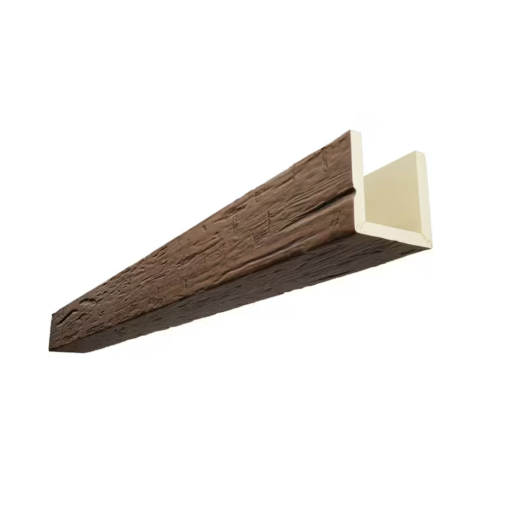
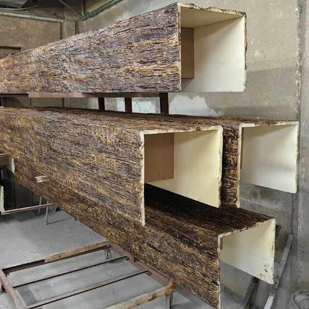
The mountain home great room featured 22-foot cathedral ceilings soaring above the main living space—impressive volume demanding architectural drama proportional to its scale. The architect designed X-brace patterns with diagonal beams crossing between ridge and side walls creating dynamic geometric composition. However, nobody had detailed connection points where diagonal beams intersected each other and how they'd attach to sloped ceilings at varying angles. During installation, we discovered that each diagonal beam required custom angle cuts at every intersection and mounting point—over 80 unique angle combinations across the ceiling. The field carpentry required to achieve these intersections added three weeks and $15,000 to the project. That expensive lesson taught me that geometric pattern complexity demands engineering during design, not problem-solving during installation.
X-brace and cross-beam pattern engineering for cathedral ceilings requires understanding geometric relationships, structural load paths, and connection details enabling successful installation. These dramatic patterns create architectural interest proportional to tall spaces but demand systematic planning preventing installation chaos when geometry and structure remain unresolved until field work begins.
Understanding Cathedral Ceiling Geometry
Pitch and slope relationships define cathedral ceiling geometries through rise-over-run ratios—perhaps 6:12 (6 inches rise per 12 inches horizontal run) creating 26.6° angles or 8:12 creating 33.7° angles. Understanding actual angles versus typical framing nomenclature proves essential for calculating diagonal beam lengths and intersection angles.
Ridge and eave dimensions establishing ceiling spans and heights determine beam lengths and pattern proportions. A 24-foot span with 8-foot rise creates different geometry than 30-foot span with 10-foot rise despite similar proportions. Actual dimensions affect not just scale but geometric relationships throughout patterns.
Symmetry considerations in cathedral ceilings typically create mirrored geometry on opposite roof slopes. X-brace patterns should respect this symmetry creating balanced compositions. Asymmetric patterns risk appearing accidental rather than intentional unless deliberately asymmetric for specific design reasons.
Three-dimensional planning recognizing cathedral ceilings as complex spatial volumes rather than flat planes proves essential for pattern design. Beams crossing in plan might not actually intersect in three-dimensional space if attaching at different ceiling heights. Understanding spatial relationships prevents two-dimensional plans that prove impossible executing in three-dimensional reality.
Geometric Layout Fundamentals
Diagonal beam angles for X-patterns crossing between ridge and eaves require calculating based on horizontal span and vertical rise. Using trigonometry: angle = arctan(rise/half-span). For 24-foot span with 8-foot rise: angle = arctan(8/12) = 33.7°. These calculations establish beam orientation angles at mounting points.
Intersection point geometry where diagonal beams cross requires calculating three-dimensional coordinates. Beams might intersect at ridge peak or at points along sloped ceilings. Each intersection point has specific X, Y, Z coordinates determining beam lengths and cut angles. CAD modeling proves invaluable for complex patterns.
Beam length calculations for diagonal spans use Pythagorean theorem accounting for horizontal distance and vertical rise. Diagonal length = √(horizontal² + vertical²). For beam spanning from eave to ridge 12 feet horizontally and 8 feet vertically: length = √(144 + 64) = 14.4 feet. Accurate length calculations prevent ordering incorrect beam sizes.
Compound angle cutting where beams mount to sloped ceilings at non-perpendicular angles requires compound miter calculations. Simple miter saws can't achieve these cuts—compound miter saws set to specific blade tilt and miter angles or careful jig work enables proper cuts. Understanding compound angles prevents improper cuts wasting materials.
Pattern spacing and proportion determining how many X-patterns across ceiling span affects visual rhythm and structural requirements. Tighter spacing creates busier appearance while wider spacing provides bold simplicity. Proportional spacing—perhaps X-patterns every 6-8 feet—creates comfortable rhythm scaled to ceiling dimensions.

Structural Load Considerations
Self-weight distribution in diagonal configurations creates different load patterns than horizontal beams. Diagonal beams transfer loads along their lengths to support points at ridge and eaves. Understanding load paths guides appropriate mounting strength at these attachment points.
Point loads at intersections where crossing beams meet create concentrated loads requiring adequate local support. If beams truly structural, intersection points need engineering ensuring structural adequacy. Even decorative beams create point loads that mounting systems must support preventing deflection or failure.
Triangulation effects where diagonal bracing creates triangulated frames provide inherent stability. Unlike parallel beam systems, X-bracing creates geometric stability through triangulation. However, this structural advantage requires connections transmitting forces through intersections—decorative beams simply overlaying might not achieve triangulation benefits.
Ceiling framing compatibility ensuring decorative beam loads transfer to actual structural framing rather than just ceiling finishes prevents ceiling damage. Cathedral ceiling framing typically uses collar ties, rafter ties, or engineered trusses—beam mounting must connect to structural elements rather than just drywall or finish materials.
Seismic and wind considerations in regions with seismic activity or high winds require evaluating whether decorative beam patterns might shift or fail during events. While decorative beams don't provide structural support, they shouldn't become hazards. Adequate fastening prevents beams becoming projectiles during extreme events.
Connection and Intersection Detailing
Overlapping joints where crossing beams simply overlap provide simplest connection approach. One beam mounts to ceiling with second beam mounting over first creating layered intersection. This approach requires minimal cutting but creates depth at intersections that might appear bulky depending on beam sizes.
Mitered intersections using 45° miter cuts at crossing points create flush intersections where beam faces align in single plane. Mitered connections require precise cutting and careful installation but achieve refined appearance. This approach suits visible intersections where finish quality matters critically.
Half-lap joints where each beam notches halfway through creating flush intersection distributes loads across joint area while maintaining visual continuity. True half-lap joints in structural applications provide excellent load transfer. For decorative beams, appearance of half-lap joints might be achieved through careful cutting and layering.
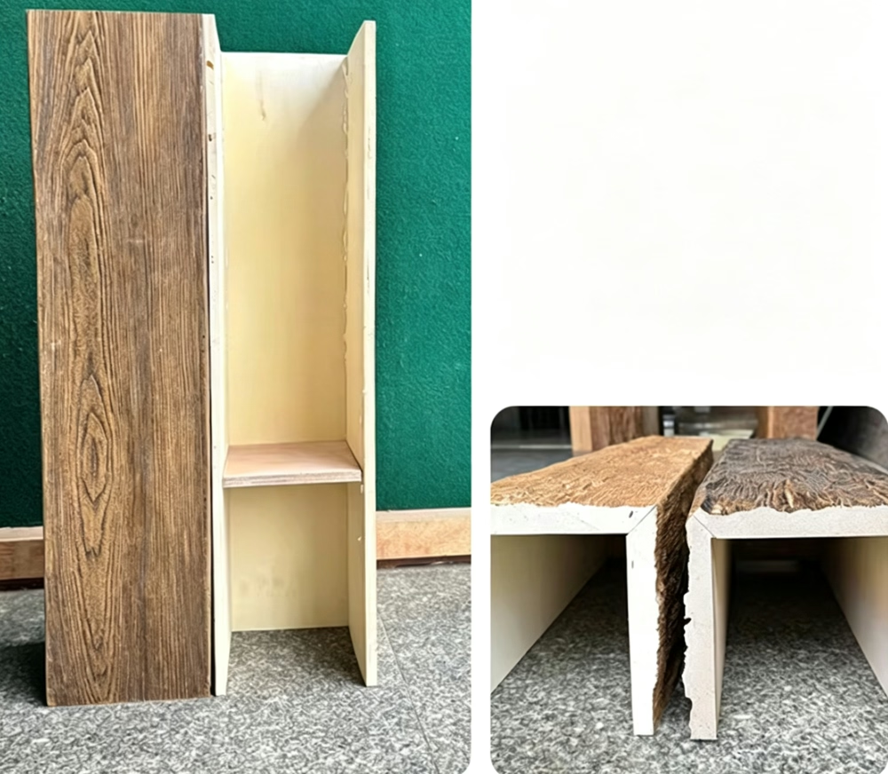
Mechanical fastening at intersections using screws, bolts, or specialty brackets secures crossing beams preventing shifting. Mechanical connections at intersections plus proper ceiling attachment creates stable beam assemblies. Concealing fasteners within decorative beam profiles maintains appearance while providing connection strength.
Decorative rosettes or medallions at intersections can celebrate connection points rather than concealing them. Architectural traditions sometimes emphasize connections through decorative elements. Rosettes or custom fabricated plates at intersections create focal points transforming technical necessities into design features.
Mounting System Design
Ridge attachment methods for beams terminating at ceiling peaks require secure connection to ridge structure. Ridge beams, rafters, or structural roof elements provide attachment—not just ceiling finish materials. Blocking, brackets, or direct connection to framing ensures adequate support.
Eave and wall attachments where diagonal beams meet ceiling edges near walls require different connection strategies than ridge attachments. Wall plates, blocking, or specialized brackets accommodate beam angle and weight. Understanding actual framing at eaves guides appropriate attachment methods.
Intermediate support for long diagonal spans might require additional support points beyond just end connections. Support points along beam lengths can prevent deflection in long spans. However, intermediate supports complicate installation and must appear intentional rather than afterthought additions.
Adjustable connections using slotted holes or adjustable brackets accommodate field variations from theoretical geometry. Real buildings never match drawings perfectly—adjustability allows accommodating small variations without requiring perfect conditions. This flexibility prevents installation paralysis when actual conditions vary from plans.
Installation Sequencing
Baseline establishment using laser levels or precise measuring establishes reference points throughout ceiling from which all pattern geometry derives. Without accurate baseline, cumulative errors create pattern geometry that doesn't close properly. Initial precision prevents pattern distortions.
Primary beam installation beginning with main structural or visual elements—perhaps ridge beams or primary diagonal members—establishes pattern framework to which subsequent elements relate. Installing framework first provides references for secondary elements.
Secondary element integration adding crossing beams to primary framework completes patterns. Secondary installation requires field-fitting to actual primary beam positions rather than purely working from plans. Allowing field adjustment accommodates real conditions while maintaining pattern integrity.
Progressive verification checking pattern geometry and appearance after each addition prevents cumulative errors. Stepping back periodically during installation reveals whether patterns read correctly from viewing distances. Real-time verification enables adjustments before problems compound.
Temporary support during installation holding beams in position while fastening occurs prevents shifting and ensures proper positioning. Adjustable supports, temporary bracing, or helper assistance maintains alignment during fastening. Proper temporary support prevents misalignment from beams shifting during installation.
Complex Pattern Variations
Multiple X-patterns creating repeating diagonal crosses across ceiling spans requires maintaining consistent geometry across multiple pattern repetitions. Pattern consistency prevents geometric drift where later patterns distort from first patterns. Systematic layout and frequent verification maintains consistency.
Asymmetric patterns intentionally violating symmetry for design effect require particularly careful planning ensuring asymmetry appears intentional rather than erroneous. Successful asymmetry requires confident execution—tentative asymmetry appears like mistakes rather than design decisions.
Curved cathedral ceilings incorporating barrel vaults or curved slopes add geometric complexity beyond straight gable forms. X-brace patterns on curved ceilings require three-dimensional modeling and potentially curved beam elements. This complexity demands CAD modeling and careful shop fabrication rather than field layout.
Mixed patterns combining X-braces with parallel beams, grids, or other elements requires coordinating different geometric systems creating unified compositions. Transitioning between pattern types or combining elements needs deliberate planning preventing visual confusion from incompatible geometries.
Digital Design and Modeling Tools
CAD modeling using three-dimensional software enables visualizing complex patterns before construction. SketchUp, Revit, or specialized timber framing software can model cathedral ceiling geometries, beam patterns, and intersection details. Digital modeling reveals geometric conflicts impossible seeing in two-dimensional drawings.
Parametric design tools allowing adjusting parameters—ceiling pitch, span, beam size—and automatically updating geometry accelerates design exploration. Rather than recalculating manually for each iteration, parametric models adjust automatically enabling rapid design refinement.
CNC fabrication for complex cuts uses digital models driving cutting equipment achieving precision impossible through manual methods. Custom brackets, complex beam end cuts, or decorative elements can CNC fabricate from digital models. This digital-to-physical workflow suits complex custom work justifying fabrication setup costs.
Virtual reality visualization using VR technology enables experiencing cathedral ceiling spaces before construction. Architects and clients can "stand" in spaces evaluating whether patterns achieve intended effects at actual scale. VR proves particularly valuable for cathedral ceilings where scale proves difficult appreciating through conventional drawings or models.
Field Adjustment Techniques
Scribing and fitting traditional carpentry techniques adapting pieces to actual conditions enables achieving tight fits despite geometric complexity and field variations. Skilled carpenters can scribe diagonal beams to actual ceiling angles achieving quality fits without relying solely on calculated angles.
Shims and adjustments accommodate small variations using shim materials correcting minor misalignments. However, shimming should remain modest—excessive shimming indicates fundamental problems requiring investigation rather than just patching symptoms.
Gap management where intersections don't achieve perfect closure uses decorative treatments transforming gaps from problems into design features. Small gaps at intersections might receive decorative banding, trim pieces, or simply caulking and painting creating acceptable appearance from imperfect geometry.
Quality Control and Verification
Pattern geometry verification checking that diagonal angles, intersection points, and overall composition match design intent prevents pattern distortions. Measuring key dimensions and comparing to plans catches deviations while correction remains possible.
Visual assessment from intended viewing locations evaluating whether patterns read correctly from actual viewing positions proves ultimate quality test. Patterns might measure correctly but appear distorted from certain angles. Assessing from actual viewing positions reveals perceptual issues that measurements miss.
Structural integrity checks ensuring all connections provide adequate support prevents safety hazards from inadequate fastening. Load testing or engineering verification provides confidence that decorative elements won't fail creating hazards.
Common Problems and Solutions
Pattern drift where sequential elements progressively deviate from layout plans accumulates through cumulative small errors. Preventing drift requires frequent measurement back to baseline references rather than measuring from previous elements where errors accumulate.
Intersection misalignment where crossing beams don't meet properly creates obvious flaws in geometric patterns. Careful layout and progressive verification during installation prevents misalignment that becomes obvious when patterns complete.
Inadequate planning attempting to resolve complex geometry during installation rather than during design creates expensive field problems, wasted materials, and schedule delays. Front-loading geometric resolution into design phase prevents construction chaos.
Cost and Schedule Implications
Design time investment in engineering patterns before construction prevents orders-of-magnitude greater costs during installation. Perhaps 10-20 hours design and engineering time prevents weeks of installation delay and thousands of dollars field problem-solving. This investment proves extremely cost-effective.
Material waste from incorrect cuts increases when complex geometry requires custom cutting. Providing accurate cutting templates, diagrams, or even CNC-cut pieces reduces waste from cutting errors. Planning reduces waste from 15-20% to 5-7% typical of simpler work.
Installation time for X-brace patterns might run 2-3x simple parallel beam installations due to geometric complexity, custom cutting, and careful fitting required. Understanding time requirements enables realistic scheduling and prevents unrealistic expectations about installation speed.
Professional Engineering Excellence
X-brace and cross-beam pattern engineering for cathedral ceilings demands systematic geometric analysis, structural consideration, and installation planning transforming aesthetic aspirations into buildable reality. These dramatic patterns create architectural impact proportional to tall spaces but require engineering during design preventing expensive reactive problem-solving during construction. For architects, designers, and contractors creating cathedral ceiling treatments, disciplined geometric planning, three-dimensional visualization, and systematic installation sequencing enable successful execution of complex patterns that appear effortlessly dramatic while representing carefully engineered solutions to geometric and structural challenges.
Success requires treating pattern design as serious engineering exercise rather than casual sketching assuming "contractors will figure it out." Complex geometry demands respect—inadequate planning creates foreseeable installation problems that adequate design prevents.
Technical References
ASTM standards cited in every specification
Test Data
Lab results from internal testing program
Updated 2026
Reviewed against current product specs